TVS data. What is tdx. V. silchenko, s. Vikulovo, Tyumen region
Nowadays, you can often find outdated CRT TVs in the trash; with the development of technology, they are no longer relevant, so now they are mostly getting rid of them. Perhaps everyone has seen on the back wall of such a TV an inscription in the spirit of “High voltage. Do not open". And it hangs there for a reason, because every TV with a picture tube has a very interesting little thing called TDKS. The abbreviation stands for “diode-cascade line transformer”; on a TV it serves, first of all, to generate high voltage to power the picture tube. At the output of such a transformer, you can get a constant voltage of as much as 15-20 kV. The alternating voltage from the high-voltage coil in such a transformer is increased and rectified using a built-in diode-capacitor multiplier.
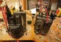
TDKS transformers look like this:

The thick red wire extending from the top of the transformer, as you might guess, is designed to remove high voltage from it. In order to start such a transformer, you need to wind your primary winding around it and assemble a simple circuit called a ZVS driver.
Scheme
The diagram is presented below:
The same diagram in another graphical representation:

A few words about the scheme. Its key link is IRF250 field-effect transistors; IRF260 are also well suited here. Instead of them, you can install other similar field-effect transistors, but these are the ones that have proven themselves best in this circuit. Between the gate of each transistor and the minus of the circuit, zener diodes are installed for a voltage of 12-18 volts; I installed zener diodes BZV85-C15, for 15 volts. Also, ultra-fast diodes, for example, UF4007 or HER108, are connected to each of the gates. A 0.68 µF capacitor is connected between the drains of the transistors for a voltage of at least 250 volts. Its capacitance is not so critical; you can safely install capacitors in the range of 0.5-1 µF. Quite significant currents flow through this capacitor, so it can heat up. It is advisable to place several capacitors in parallel, or take a capacitor for a higher voltage, 400-600 volts. There is a choke in the diagram, the rating of which is also not very critical and can be in the range of 47 - 200 µH. You can wind 30-40 turns of wire on a ferrite ring, it will work in any case.
Manufacturing


If the inductor gets very hot, then you should reduce the number of turns, or take a wire with a thicker cross-section. The main advantage of the circuit is its high efficiency, because the transistors in it hardly heat up, but, nevertheless, they should be installed on a small radiator for reliability. When installing both transistors on a common radiator, it is imperative to use a heat-conducting insulating gasket, because the metal back of the transistor is connected to its drain. The supply voltage of the circuit lies in the range of 12 - 36 volts; at a voltage of 12 volts at idle, the circuit consumes approximately 300 mA; when the arc is burning, the current rises to 3-4 amperes. The higher the supply voltage, the higher the voltage will be at the output of the transformer.
If you look closely at the transformer, you can see the gap between its body and the ferrite core is approximately 2-5 mm. The core itself needs to be wound with 10-12 turns of wire, preferably copper. The wire can be wound in any direction. The larger the wire, the better, but a wire that is too large may not fit into the gap. You can also use enameled copper wire; it will fit into even the narrowest gap. Then you need to make a tap from the middle of this winding, exposing the wires in the right place, as shown in the photo:


You can wind two windings of 5-6 turns in one direction and connect them, in this case you also get a tap from the middle.
When the circuit is turned on, an electric arc will occur between the high voltage terminal of the transformer (thick red wire at the top) and its negative terminal. The minus is one of the legs. You can determine the required minus leg quite simply by placing the “+” next to each leg in turn. The air breaks through at a distance of 1 - 2.5 cm, so a plasma arc will immediately appear between the desired leg and the plus.
You can use such a high-voltage transformer to create another interesting device - Jacob's ladder. It is enough to arrange two straight electrodes in a “V” shape, connect a plus to one, and a minus to the other. The discharge will appear at the bottom, begin to creep up, break at the top and the cycle will repeat.
You can download the board here:
(downloads: 581)
The device in question generates electrical discharges with a voltage of about 30 kV, so please exercise extreme caution during assembly, installation and further use. Even after turning off the circuit, some voltage remains in the voltage multiplier.
Of course, this voltage is not fatal, but the switched on multiplier can pose a danger to your life. Follow all safety precautions.

Now let's get down to business. To obtain high-potential discharges, components from the line scan of a Soviet television were used. I wanted to create a simple and powerful high-voltage generator powered by a 220-volt network. Such a generator was needed for experiments that I carry out regularly. The generator power is quite high, at the output of the multiplier the discharges reach up to 5-7 cm,


To power the line transformer, LDS ballast was used, which was sold separately and cost $2.


This ballast is designed to power two fluorescent lamps, each 40 watts. For each channel, 4 wires come out of the board, two of which we will call “hot”, since it is through them that the high voltage flows to power the lamp. The remaining two wires are connected to each other by a capacitor, this is necessary to start the lamp. At the output of the ballast, a high voltage with a high frequency is generated, which must be applied to a line transformer. The voltage is supplied in series through a capacitor, otherwise the ballast will burn out in a few seconds.

We select a capacitor with a voltage of 100-1500 volts, a capacity from 1000 to 6800pF.
It is not recommended to turn on the generator for a long time, or you should install transistors on the heat sinks, since after 5 seconds of operation there is already an increase in temperature.
The line transformer was used type TVS-110PTs15, voltage multiplier UN9/27-1 3.
List of radioelements
| Designation | Type | Denomination | Quantity | Note | Shop | My notepad | |
|---|---|---|---|---|---|---|---|
| Scheme of prepared ballast. | |||||||
| VT1, VT2 | Bipolar transistor | FJP13007 | 2 | To notepad | |||
| VDS1, VD1, VD2 | Rectifier diode | 1N4007 | 6 | To notepad | |||
| C1, C2 | 10 µF 400 V | 2 | To notepad | ||||
| C3, C4 | Electrolytic capacitor | 2.2 µF 50 V | 2 | To notepad | |||
| C5, C6 | Capacitor | 3300 pF 1000 V | 2 | To notepad | |||
| R1, R6 | Resistor | 10 ohm | 2 | To notepad | |||
| R2, R4 | Resistor | 510 kOhm | 2 | To notepad | |||
| R3, R5 | Resistor | 18 ohm | 2 | To notepad | |||
| Inductor | 4 | To notepad | |||||
| F1 | Fuse | 1 A | 1 | To notepad | |||
| Additional elements. | |||||||
| C1 | Capacitor | 1000-6800 pF | 1 | To notepad | |||
| Linear scan transformer | TVS-110PTs15 | 1 | To notepad | ||||
| Voltage multiplier | UN 9/27-13 | 1 | |||||
In table Table 5.15 shows the maximum possible values of the energy release and fuel assembly power non-uniformity coefficients during the campaign for typical reactor core cells. The values of the energy release unevenness coefficients were taken according to the data in Section 5.3.6, obtained by simulating successive loads of fresh fuel assemblies in each of these cells on a physical model of the reactor with an average core burnup of about 20%.
Table No. 5.15
Maximum possible power characteristics of fuel assemblies during a campaign in typical core cells
The numbers in brackets of the first line of the table. No. 5.15 correspond to the number of full-scale fuel assemblies (per 188 fuel rods) rounded to the nearest whole value, located in the energy-releasing space of the core at the time of its state, corresponding to the maximum values of the energy release non-uniformity coefficients for a typical cell. This quantity is determined by the position of the CO (the fraction of the fuel suspension introduced into the zone) and the number of fuel assemblies 184.05 (160 fuel rods) located in the core (for the data given in Table 5.15, it is assumed to be 6).
Calculations of the maximum values of temperature parameters of fuel elements that can be realized during a campaign in typical core cells for a steady-state reactor operation at a nominal power level of 100 MW were carried out using the KANAL-K program. In each fuel assembly there is a table. No. 5.15, a fragment of 8 neighboring most stressed fuel rods was calculated, including the fuel rod with the maximum energy release. The initial data and calculation results are summarized in table. No. 5.16.
Table No. 5.16
Design parameters of fuel assemblies and fuel rods at a reactor power of 100 MW
| Parameter | Meaning | ||||
| Reactor power, MW | |||||
| Coolant temperature at the entrance to the core, o C | |||||
| Coolant pressure at the reactor inlet, MPa | |||||
| Coolant temperature in the lower mixing chamber, o C | 88,5 | ||||
| Type cell number | |||||
| Coolant flow through fuel assemblies, m 3 /h | 40,2 | 49,9 | 37,8 | 65,7 | 121,8 |
| Average coolant speed, m/s | 3,9 | 4,9 | 3,7 | 6,6 | 12,0 |
| Temperature of the coolant at the outlet of the calculation cell with maximum energy release, o C | |||||
| Maximum temperature of the fuel element cladding in the cavity of the cross, o C | 300,1 | 301,1 | 298,1 | 304,7 | 313,5 |
| Maximum temperature of the fuel composition in the center of the cross, o C | 416,2 | 428,1 | 398,3 | 463,6 | 575,0 | 7,0 | 8,4 | 6,3 | 10,8 | 17,6 |
| Maximum design safety factor for critical thermal loads, Kcr | 1,51 | 1,51 | 1,51 | 1,51 | 1,51 |
As a consequence of the partial overload mode used at the SM-3 reactor, the distribution of energy releases throughout the core changes both from campaign to campaign, and during each individual campaign. During overloads, fresh fuel assemblies are installed, as a rule, two at a time in the inner and outer layers of the zone and no more than two fuel assemblies in a quadrant. During the campaign, the distribution of energy releases depends on the movement of the CPS RO, changes in the volume of the zone due to the introduction of additional fuel loads of the KO, which are uneven throughout the burnout and poisoning zone. Taking this into account, the implementation of those given in table. No. 5.16 fuel rod cooling modes in a particular set of fuel cells will also depend on the specific campaign and its course.
A feature of the operation of fuel rods in the SM-3 reactor, as in SM-2, is the use of forced cooling of the most energy-intensive fuel rods by allowing surface boiling of the coolant in all typical cells of the zone in modes with maximum energy release in the fuel assemblies of these cells (hydroprofiling ensuring the same margin up to crisis). On some of the fuel elements with maximum energy release, the temperature of the outer surface of the fuel element cladding is higher than the saturation temperature, which causes the formation of bubbles in the microcavities of its surface. In turn, underheating of the coolant to the saturation temperature leads to rapid condensation of steam bubbles, and, thus, there is no volumetric vapor content in the flow. Boiling of the coolant increases the heat transfer coefficient, which ensures that the fuel cladding temperature remains at a relatively low level. During the entire operation of the SM-2 and SM-3 reactors, no hydraulic or neutron instabilities were noted in the operation of the core and control system.
High-voltage, low-power generators are widely used in flaw detection, to power portable charged particle accelerators, X-ray and cathode ray tubes, photomultiplier tubes, and ionizing radiation detectors. In addition, they are also used for electric pulse destruction of solids, production of ultrafine powders, synthesis of new materials, as spark leak detectors, for launching gas-discharge light sources, in electric-discharge diagnostics of materials and products, obtaining gas-discharge photographs using the S. D. Kirlian method , testing the quality of high-voltage insulation. In everyday life, such devices are used as power sources for electronic traps of ultrafine and radioactive dust, electronic ignition systems, for electroeffluvial chandeliers (chandeliers by A. L. Chizhevsky), aeroionizers, medical devices (D'Arsonval, franklization, ultratonotherapy devices ), gas lighters, electric fences, electric stun guns, etc.
Conventionally, we classify as high-voltage generators devices that generate voltages above 1 kV.
The high-voltage pulse generator using a resonant transformer (Fig. 11.1) is made according to the classical scheme using a gas spark gap RB-3.
Capacitor C2 is charged with a pulsating voltage through diode VD1 and resistor R1 to the breakdown voltage of the gas spark gap. As a result of breakdown of the gas gap of the spark gap, the capacitor is discharged onto the primary winding of the transformer, after which the process is repeated. As a result, damped high-voltage pulses with an amplitude of up to 3...20 kV are formed at the output of transformer T1.
To protect the output winding of the transformer from overvoltage, a spark gap made in the form of electrodes with an adjustable air gap is connected in parallel to it.
Rice. 11.1. Circuit of a high-voltage pulse generator using a gas spark gap.

Rice. 11.2. Circuit of a high-voltage pulse generator with voltage doubling.
Transformer T1 of the pulse generator (Fig. 11.1) is made on an open ferrite core M400NN-3 with a diameter of 8 and a length of 100 mm. The primary (low-voltage) winding of the transformer contains 20 turns of MGShV wire 0.75 mm with a winding pitch of 5...6 mm. The secondary winding contains 2400 turns of ordinary winding of PEV-2 wire 0.04 mm. The primary winding is wound over the secondary winding through a 2x0.05 mm polytetrafluoroethylene (fluoroplastic) gasket. The secondary winding of the transformer must be reliably isolated from the primary.
An embodiment of a high-voltage pulse generator using a resonant transformer is shown in Fig. 11.2. In this generator circuit there is galvanic isolation from the supply network. The mains voltage is supplied to the intermediate (step-up) transformer T1. The voltage removed from the secondary winding of the network transformer is supplied to a rectifier operating according to a voltage doubling circuit.
As a result of the operation of such a rectifier, a positive voltage appears on the upper plate of capacitor C2 relative to the neutral wire, equal to the square root of 2Uii, where Uii is the voltage on the secondary winding of the power transformer.
A corresponding voltage of the opposite sign is formed at capacitor C1. As a result, the voltage on the plates of the capacitor SZ will be equal to 2 square roots of 2Uii.
The charging rate of capacitors C1 and C2 (C1=C2) is determined by the value of resistance R1.
When the voltage on the plates of capacitor SZ is equal to the breakdown voltage of the gas gap FV1, a breakdown of its gas gap will occur, capacitor SZ and, accordingly, capacitors C1 and C2 will be discharged, and periodic damped oscillations will occur in the secondary winding of transformer T2. After discharging the capacitors and turning off the spark gap, the process of charging and subsequent discharging the capacitors to the primary winding of transformer 12 will be repeated again.
A high-voltage generator used to obtain photographs in a gas discharge, as well as to collect ultrafine and radioactive dust (Fig. 11.3) consists of a voltage doubler, a relaxation pulse generator and a step-up resonant transformer.
The voltage doubler is made using diodes VD1, VD2 and capacitors C1, C2. The charging chain is formed by capacitors C1 SZ and resistor R1. A 350 V gas spark gap is connected in parallel to capacitors C1 SZ with the primary winding of step-up transformer T1 connected in series.
As soon as the DC voltage level on capacitors C1 SZ exceeds the breakdown voltage of the spark gap, the capacitors are discharged through the winding of the step-up transformer and as a result a high-voltage pulse is formed. The circuit elements are selected so that the pulse formation frequency is about 1 Hz. Capacitor C4 is designed to protect the output terminal of the device from mains voltage.

Rice. 11.3. Circuit of a high voltage pulse generator using a gas spark gap or dinistors.
The output voltage of the device is entirely determined by the properties of the transformer used and can reach 15 kV. A high-voltage transformer with an output voltage of about 10 kV is made on a dielectric tube with an outer diameter of 8 and a length of 150 mm; a copper electrode with a diameter of 1.5 mm is located inside. The secondary winding contains 3...4 thousand turns of PELSHO 0.12 wire, wound turn to turn in 10...13 layers (winding width 70 mm) and impregnated with BF-2 glue with interlayer insulation made of polytetrafluoroethylene. The primary winding contains 20 turns of PEV 0.75 wire passed through a polyvinyl chloride cambric.
As such a transformer, you can also use a modified horizontal scan output transformer of a TV; transformers for electronic lighters, flash lamps, ignition coils, etc.
The R-350 gas discharger can be replaced by a switchable chain of dinistors of the KN102 type (Fig. 11.3, right), which will allow the output voltage to be changed stepwise. To evenly distribute the voltage across the dinistors, resistors of the same value with a resistance of 300...510 kOhm are connected in parallel to each of them.
A variant of the high-voltage generator circuit using a gas-filled device, a thyratron, as a threshold-switching element is shown in Fig. 11.4.

Rice. 11.4. Circuit of a high voltage pulse generator using a thyratron.
The mains voltage is rectified by diode VD1. The rectified voltage is smoothed by capacitor C1 and supplied to the charging circuit R1, C2. As soon as the voltage on capacitor C2 reaches the ignition voltage of thyratron VL1, it flashes. Capacitor C2 is discharged through the primary winding of transformer T1, the thyratron goes out, the capacitor begins to charge again, etc.
An automobile ignition coil is used as transformer T1.
Instead of the VL1 MTX-90 thyratron, you can turn on one or more KN102 type dinistors. The amplitude of the high voltage can be adjusted by the number of included dinistors.
The design of a high-voltage converter using a thyratron switch is described in the work. Note that other types of gas-filled devices can be used to discharge a capacitor.
More promising is the use of semiconductor switching devices in modern high-voltage generators. Their advantages are clearly expressed: high repeatability of parameters, lower cost and dimensions, high reliability.
Below we will consider high-voltage pulse generators using semiconductor switching devices (dinistors, thyristors, bipolar and field-effect transistors).
A completely equivalent, but low-current analogue of gas dischargers are dinistors.
In Fig. Figure 11.5 shows the electrical circuit of a generator made on dinistors. The structure of the generator is completely similar to those described earlier (Fig. 11.1, 11.4). The main difference is the replacement of the gas discharger with a chain of dinistors connected in series.

Rice. 11.5. Circuit of a high-voltage pulse generator using dinistors.

Rice. 11.6. Circuit of a high-voltage pulse generator with a bridge rectifier.
It should be noted that the efficiency of such an analogue and switched currents are noticeably lower than that of the prototype, however, dinistors are more affordable and more durable.
A somewhat complicated version of the high-voltage pulse generator is shown in Fig. 11.6. The mains voltage is supplied to a bridge rectifier using diodes VD1 VD4. The rectified voltage is smoothed out by capacitor C1. This capacitor generates a constant voltage of about 300 V, which is used to power a relaxation generator composed of elements R3, C2, VD5 and VD6. Its load is the primary winding of transformer T1. Pulses with an amplitude of approximately 5 kV and a repetition frequency of up to 800 Hz are removed from the secondary winding.
The chain of dinistors must be designed for a switching voltage of about 200 V. Here you can use dinistors of the KN102 or D228 type. It should be taken into account that the switching voltage of dinistors of type KN102A, D228A is 20 V; KN102B, D228B 28 V; KN102V, D228V 40 V; KN102G, D228G 56 V; KN102D, D228D 80 V; KN102E 75 V; KN102Zh, D228Zh 120 V; KN102I, D228I 150 V.
A modified line transformer from a black-and-white TV can be used as a T1 transformer in the above devices. Its high-voltage winding is left, the rest are removed and instead a low-voltage (primary) winding is wound 15...30 turns of PEV wire with a diameter of 0.5...0.8 mm.
When choosing the number of turns of the primary winding, the number of turns of the secondary winding should be taken into account. It is also necessary to keep in mind that the value of the output voltage of the high-voltage pulse generator depends to a greater extent on the adjustment of the transformer circuits to resonance rather than on the ratio of the number of turns of the windings.
The characteristics of some types of horizontal scanning television transformers are given in Table 11.1.
Table 11.1. Parameters of high-voltage windings of unified horizontal television transformers.
| Transformer type | Number of turns | R windings, Ohm |
|
| TVS-A, TVS-B | |||
| TVS-110, TVS-110M | |||
| Transformer type | Number of turns | R windings, Ohm |
|
| TVS-90LTs2, TVS-90LTs2-1 | |||
| TVS-110PTs15 | |||
| TVS-110PTs16, TVS-110PTs18 |

Rice. 11.7. Electrical circuit of a high-voltage pulse generator.
In Fig. Figure 11.7 shows a diagram of a two-stage high-voltage pulse generator published on one of the sites, in which a thyristor is used as a switching element. In turn, a gas-discharge device neon lamp (chain HL1, HL2) was chosen as a threshold element that determines the repetition rate of high-voltage pulses and triggers the thyristor.
When supply voltage is applied, the pulse generator, made on the basis of transistor VT1 (2N2219A KT630G), produces a voltage of about 150 V. This voltage is rectified by diode VD1 and charges capacitor C2.
After the voltage on capacitor C2 exceeds the ignition voltage of neon lamps HL1, HL2, the capacitor will be discharged through the current-limiting resistor R2 to the control electrode of thyristor VS1, and the thyristor will be unlocked. The discharge current of capacitor C2 will create electrical oscillations in the primary winding of transformer T2.
The thyristor switching voltage can be adjusted by selecting neon lamps with different ignition voltages. You can change the thyristor turn-on voltage stepwise by switching the number of neon lamps connected in series (or dinistors replacing them).

Rice. 11.8. Diagram of electrical processes on the electrodes of semiconductor devices (to Fig. 11.7).
The voltage diagram at the base of transistor VT1 and at the anode of the thyristor is shown in Fig. 11.8. As follows from the presented diagrams, the blocking generator pulses have a duration of approximately 8 ms. Capacitor C2 is charged exponentially in accordance with the action of pulses taken from the secondary winding of transformer T1.
Pulses with a voltage of approximately 4.5 kV are formed at the output of the generator. The output transformer for low-frequency amplifiers is used as transformer T1. As
High-voltage transformer T2 uses a transformer from a photo flash or a recycled (see above) horizontal scanning television transformer.
The diagram of another version of the generator using a neon lamp as a threshold element is shown in Fig. 11.9.

Rice. 11.9. Electrical circuit of a generator with a threshold element on a neon lamp.
The relaxation generator in it is made on elements R1, VD1, C1, HL1, VS1. It operates at positive line voltage cycles, when capacitor C1 is charged to the switching voltage of the threshold element on the neon lamp HL1 and thyristor VS1. Diode VD2 dampens self-induction pulses of the primary winding of step-up transformer T1 and allows you to increase the output voltage of the generator. The output voltage reaches 9 kV. The neon lamp also serves as an indicator that the device is connected to the network.
The high-voltage transformer is wound on a piece of rod with a diameter of 8 and a length of 60 mm made of M400NN ferrite. First, a primary winding of 30 turns of PELSHO 0.38 wire is placed, and then a secondary winding of 5500 turns of PELSHO 0.05 or larger diameter is placed. Between the windings and every 800... 1000 turns of the secondary winding, an insulation layer of polyvinyl chloride insulating tape is laid.
In the generator, it is possible to introduce discrete multi-stage adjustment of the output voltage by switching neon lamps or dinistors in a series circuit (Fig. 11.10). In the first version, two stages of regulation are provided, in the second - up to ten or more (when using KN102A dinistors with a switching voltage of 20 V).

Rice. 11.10. Electrical circuit of the threshold element.

Rice. 11.11. Electrical circuit of a high voltage generator with a diode threshold element.
A simple high-voltage generator (Fig. 11.11) allows you to obtain output pulses with an amplitude of up to 10 kV.
The control element of the device switches with a frequency of 50 Hz (at one half-wave of the mains voltage). The diode VD1 D219A (D220, D223) operating under reverse bias in avalanche breakdown mode was used as a threshold element.
When the avalanche breakdown voltage at the semiconductor junction of the diode exceeds the avalanche breakdown voltage, the diode transitions to a conducting state. The voltage from the charged capacitor C2 is supplied to the control electrode of the thyristor VS1. After turning on the thyristor, capacitor C2 is discharged into the winding of transformer T1.
Transformer T1 does not have a core. It is made on a reel with a diameter of 8 mm from polymethyl methacrylate or polytetrachlorethylene and contains three spaced sections with a width of
9 mm. The step-up winding contains 3x1000 turns, wound with PET, PEV-2 0.12 mm wire. After winding, the winding must be soaked in paraffin. 2 x 3 layers of insulation are applied on top of the paraffin, after which the primary winding is wound with 3 x 10 turns of PEV-2 0.45 mm wire.
Thyristor VS1 can be replaced with another one for a voltage higher than 150 V. The avalanche diode can be replaced with a chain of dinistors (Fig. 11.10, 11.11 below).
The circuit of a low-power portable high-voltage pulse source with autonomous power supply from one galvanic element (Fig. 11.12) consists of two generators. The first is built on two low-power transistors, the second on a thyristor and a dinistor.

Rice. 11.12. Voltage generator circuit with low-voltage power supply and thyristor-dinistor key element.
A cascade of transistors of different conductivities converts low-voltage direct voltage into high-voltage pulsed voltage. The timing chain in this generator is the elements C1 and R1. When the power is turned on, transistor VT1 opens, and the voltage drop across its collector opens transistor VT2. Capacitor C1, charging through resistor R1, reduces the base current of transistor VT2 so much that transistor VT1 comes out of saturation, and this leads to the closing of VT2. The transistors will be closed until capacitor C1 is discharged through the primary winding of transformer T1.
The increased pulse voltage removed from the secondary winding of transformer T1 is rectified by diode VD1 and supplied to capacitor C2 of the second generator with thyristor VS1 and dinistor VD2. In every positive half-cycle
The storage capacitor C2 is charged to an amplitude voltage value equal to the switching voltage of the dinistor VD2, i.e. up to 56 V (nominal pulse unlocking voltage for dinistor type KN102G).
The transition of the dinistor to the open state affects the control circuit of the thyristor VS1, which in turn also opens. Capacitor C2 is discharged through the thyristor and the primary winding of transformer T2, after which the dinistor and thyristor close again and the next capacitor charge begins; the switching cycle is repeated.
Pulses with an amplitude of several kilovolts are removed from the secondary winding of transformer T2. The frequency of spark discharges is approximately 20 Hz, but it is much less than the frequency of the pulses taken from the secondary winding of transformer T1. This happens because capacitor C2 is charged to the dinistor switching voltage not in one, but in several positive half-cycles. The capacitance value of this capacitor determines the power and duration of the output discharge pulses. The average value of the discharge current that is safe for the dinistor and the control electrode of the thyristor is selected based on the capacitance of this capacitor and the magnitude of the pulse voltage supplying the cascade. To do this, the capacitance of capacitor C2 should be approximately 1 µF.
Transformer T1 is made on a ring ferrite magnetic core of type K10x6x5. It has 540 turns of PEV-2 0.1 wire with a grounded tap after the 20th turn. The beginning of its winding is connected to the transistor VT2, the end to the diode VD1. Transformer T2 is wound on a coil with a ferrite or permalloy core with a diameter of 10 mm and a length of 30 mm. A coil with an outer diameter of 30 mm and a width of 10 mm is wound with PEV-2 0.1 mm wire until the frame is completely filled. Before winding is completed, a grounded tap is made, and the last row of wire of 30...40 turns is wound turn to turn over an insulating layer of varnished cloth.
The T2 transformer must be impregnated with insulating varnish or BF-2 glue during winding, then thoroughly dried.
Instead of VT1 and VT2, you can use any low-power transistors capable of operating in pulse mode. Thyristor KU101E can be replaced with KU101G. Power source galvanic cells with a voltage of no more than 1.5 V, for example, 312, 314, 316, 326, 336, 343, 373, or nickel-cadmium disk batteries type D-0.26D, D-0.55S and so on.
A thyristor generator of high-voltage pulses with mains power is shown in Fig. 11.13.

Rice. 11.13. Electrical circuit of a high-voltage pulse generator with a capacitive energy storage device and a thyristor switch.
During the positive half-cycle of the mains voltage, capacitor C1 is charged through resistor R1, diode VD1 and the primary winding of transformer T1. Thyristor VS1 is closed in this case, since there is no current through its control electrode (the voltage drop across diode VD2 in the forward direction is small compared to the voltage required to open the thyristor).
During a negative half-cycle, diodes VD1 and VD2 close. A voltage drop is formed at the cathode of the thyristor relative to the control electrode (minus at the cathode, plus at the control electrode), a current appears in the control electrode circuit, and the thyristor opens. At this moment, capacitor C1 is discharged through the primary winding of the transformer. A high voltage pulse appears in the secondary winding. And so on every period of mains voltage.
At the output of the device, bipolar high-voltage pulses are formed (since damped oscillations occur when the capacitor is discharged in the primary winding circuit).
Resistor R1 can be composed of three parallel-connected MLT-2 resistors with a resistance of 3 kOhm.
Diodes VD1 and VD2 must be designed for a current of at least 300 mA and a reverse voltage of at least 400 V (VD1) and 100 B (VD2). Capacitor C1 of the MBM type for a voltage of at least 400 V. Its capacitance (a fraction of a unit of microfarad) is selected experimentally. Thyristor VS1 type KU201K, KU201L, KU202K KU202N. Transformators B2B ignition coil (6 V) from a motorcycle or car.
The device can use a horizontal scanning television transformer TVS-110L6, TVS-1 YULA, TVS-110AM.
A fairly typical circuit of a high-voltage pulse generator with a capacitive energy storage device is shown in Fig. 11.14.

Rice. 11.14. Scheme of a thyristor generator of high-voltage pulses with a capacitive energy storage device.
The generator contains a quenching capacitor C1, a diode rectifier bridge VD1 VD4, a thyristor switch VS1 and a control circuit. When the device is turned on, capacitors C2 and S3 are charged, thyristor VS1 is still closed and does not conduct current. The maximum voltage on capacitor C2 is limited by a zener diode VD5 of 9V. In the process of charging capacitor C2 through resistor R2, the voltage at potentiometer R3 and, accordingly, at the control transition of thyristor VS1 increases to a certain value, after which the thyristor switches to a conducting state, and capacitor SZ through thyristor VS1 is discharged through the primary (low-voltage) winding of transformer T1, generating a high voltage pulse. After this, the thyristor closes and the process begins again. Potentiometer R3 sets the response threshold of thyristor VS1.
The pulse repetition rate is 100 Hz. An automobile ignition coil can be used as a high-voltage transformer. In this case, the output voltage of the device will reach 30...35 kV. The thyristor generator of high-voltage pulses (Fig. 11.15) is controlled by voltage pulses taken from a relaxation generator made on dinistor VD1. The operating frequency of the control pulse generator (15...25 Hz) is determined by the value of resistance R2 and the capacitance of capacitor C1.

Rice. 11.15. Electrical circuit of a thyristor high-voltage pulse generator with pulse control.
The relaxation generator is connected to the thyristor switch through a pulse transformer T1 type MIT-4. A high-frequency transformer from the Iskra-2 darsonvalization apparatus is used as the output transformer T2. The voltage at the device output can reach 20...25 kV.
In Fig. Figure 11.16 shows an option for supplying control pulses to thyristor VS1.
The voltage converter (Fig. 11.17), developed in Bulgaria, contains two stages. In the first of them, the load of the key element, made on the transistor VT1, is the winding of the transformer T1. Rectangular control pulses periodically turn on/off the switch on transistor VT1, thereby connecting/disconnecting the primary winding of the transformer.

Rice. 11.16. Option for controlling a thyristor switch.

Rice. 11.17. Electrical circuit of a two-stage high-voltage pulse generator.
An increased voltage is induced in the secondary winding, proportional to the transformation ratio. This voltage is rectified by diode VD1 and charges capacitor C2, which is connected to the primary (low-voltage) winding of high-voltage transformer T2 and thyristor VS1. The operation of the thyristor is controlled by voltage pulses taken from the additional winding of transformer T1 through a chain of elements that correct the shape of the pulse.
As a result, the thyristor periodically turns on/off. Capacitor C2 is discharged onto the primary winding of the high-voltage transformer.
High-voltage pulse generator, fig. 11.18, contains a generator based on a unijunction transistor as a control element.

Rice. 11.18. Circuit of a high-voltage pulse generator with a control element based on a unijunction transistor.
The mains voltage is rectified by the diode bridge VD1 VD4. The ripples of the rectified voltage are smoothed out by capacitor C1; the charging current of the capacitor at the moment the device is connected to the network is limited by resistor R1. Through resistor R4, capacitor S3 is charged. At the same time, a pulse generator based on a unijunction transistor VT1 comes into operation. Its “trigger” capacitor C2 is charged through resistors R3 and R6 from a parametric stabilizer (ballast resistor R2 and zener diodes VD5, VD6). As soon as the voltage on capacitor C2 reaches a certain value, transistor VT1 switches, and an opening pulse is sent to the control transition of thyristor VS1.
Capacitor SZ is discharged through thyristor VS1 to the primary winding of transformer T1. A high voltage pulse is formed on its secondary winding. The repetition rate of these pulses is determined by the frequency of the generator, which, in turn, depends on the parameters of the chain R3, R6 and C2. Using the tuning resistor R6, you can change the output voltage of the generator by about 1.5 times. In this case, the pulse frequency is regulated within the range of 250... 1000 Hz. In addition, the output voltage changes when selecting resistor R4 (ranging from 5 to 30 kOhm).
It is advisable to use paper capacitors (C1 and SZ for a rated voltage of at least 400 V); The diode bridge must be designed for the same voltage. Instead of what is indicated in the diagram, you can use the T10-50 thyristor or, in extreme cases, KU202N. Zener diodes VD5, VD6 should provide a total stabilization voltage of about 18 V.
The transformer is made on the basis of TVS-110P2 from black and white televisions. All primary windings are removed and 70 turns of PEL or PEV wire with a diameter of 0.5...0.8 mm are wound onto the vacant space.
Electrical circuit of a high voltage pulse generator, Fig. 11.19, consists of a diode-capacitor voltage multiplier (diodes VD1, VD2, capacitors C1 C4). Its output produces a constant voltage of approximately 600 V.

Rice. 11.19. Circuit of a high-voltage pulse generator with a mains voltage doubler and a trigger pulse generator based on a unijunction transistor.
A unijunction transistor VT1 type KT117A is used as a threshold element of the device. The voltage at one of its bases is stabilized by a parametric stabilizer based on a VD3 zener diode of type KS515A (stabilization voltage 15 B). Through resistor R4, capacitor C5 is charged, and when the voltage at the control electrode of transistor VT1 exceeds the voltage at its base, VT1 switches to a conducting state, and capacitor C5 is discharged to the control electrode of thyristor VS1.
When the thyristor is turned on, the chain of capacitors C1 C4, charged to a voltage of about 600...620 V, is discharged into the low-voltage winding of the step-up transformer T1. After this, the thyristor turns off, the charge-discharge processes are repeated with a frequency determined by the constant R4C5. Resistor R2 limits the short circuit current when the thyristor is turned on and at the same time is an element of the charging circuit of capacitors C1 C4.
The converter circuit (Fig. 11.20) and its simplified version (Fig. 11.21) is divided into the following components: network suppression filter (interference filter); electronic regulator; high voltage transformer.

Rice. 11.20. Electrical circuit of a high voltage generator with a surge protector.

Rice. 11.21. Electrical circuit of a high voltage generator with a surge protector.
Scheme in Fig. 11.20 works as follows. The capacitor SZ is charged through the diode rectifier VD1 and resistor R2 to the amplitude value of the network voltage (310 V). This voltage passes through the primary winding of transformer T1 to the anode of thyristor VS1. Along the other branch (R1, VD2 and C2), capacitor C2 is slowly charged. When, during its charging, the breakdown voltage of dinistor VD4 is reached (within 25...35 V), capacitor C2 is discharged through the control electrode of thyristor VS1 and opens it.
Capacitor SZ is almost instantly discharged through the open thyristor VS1 and the primary winding of transformer T1. The pulsed changing current induces a high voltage in the secondary winding T1, the value of which can exceed 10 kV. After the discharge of the capacitor SZ, the thyristor VS1 closes and the process repeats.
A television transformer is used as a high-voltage transformer, from which the primary winding is removed. For the new primary winding, a winding wire with a diameter of 0.8 mm is used. Number of turns 25.
For the manufacture of barrier filter inductors L1, L2, high-frequency ferrite cores are best suited, for example, 600NN with a diameter of 8 mm and a length of 20 mm, each having approximately 20 turns of winding wire with a diameter of 0.6...0.8 mm.

Rice. 11.22. Electrical circuit of a two-stage high-voltage generator with a field-effect transistor control element.
A two-stage high-voltage generator (author Andres Estaban de la Plaza) contains a transformer pulse generator, a rectifier, a timing RC circuit, a key element on a thyristor (triac), a high-voltage resonant transformer and a thyristor operation control circuit (Fig. 11.22).
Analogue of transistor TIP41 KT819A.
A low-voltage transformer voltage converter with cross-feedback, assembled on transistors VT1 and VT2, produces pulses with a repetition frequency of 850 Hz. To facilitate operation when large currents flow, transistors VT1 and VT2 are installed on radiators made of copper or aluminum.
The output voltage removed from the secondary winding of transformer T1 of the low-voltage converter is rectified by the diode bridge VD1 VD4 and charges capacitors S3 and C4 through resistor R5.
The thyristor switching threshold is controlled by a voltage regulator, which includes a field-effect transistor VTZ.
Further, the operation of the converter does not differ significantly from the previously described processes: periodic charging/discharging of capacitors occurs on the low-voltage winding of the transformer, and damped electrical oscillations are generated. The output voltage of the converter, when used at the output as a step-up transformer of an ignition coil from a car, reaches 40...60 kV at a resonant frequency of approximately 5 kHz.
Transformer T1 (output horizontal scan transformer) contains 2x50 turns of wire with a diameter of 1.0 mm, wound bifilarly. The secondary winding contains 1000 turns with a diameter of 0.20...0.32 mm.
Note that modern bipolar and field-effect transistors can be used as controlled key elements.
Replacing a line transformer in an MC6105 television monitor with a 31LK kinescope is, of course, not a major overhaul. Moreover: if the monitor’s old standard “lineman” does the job, then it’s hardly advisable to change this (very expensive, “capricious” and hygroscopic) unit to a new one.
It should also be borne in mind that the procured TDKS-8 may turn out to be no better than the previous, prematurely “failed” line transformer. Therefore, it is worth looking for a more worthy replacement. This is, as evidenced by comparative data (see figure), a line transformer TVS-90P4 with a double voltage multiplier UN9/18-0.3 or an even cheaper “line transformer” TVS-90PTs8. The latter, however, has an additional remote coil, but it does not have any practical effect on the image. Moreover, the mentioned transformers have the same ferrite cores, so the failed TDKS-8 can not be thrown away, but TVS-90P4 can be made from it, having previously fired it to destroy the plastic filling and windings on an electric stove (in the open air!) or in the flame of a fire.
It should be noted that in the case of using a voltage multiplier UN9/27 (three-fold action), the winding data for the TVS-90P4 (Table 1) remains unchanged, with the exception of the winding with pins 9-10. It contains 1266 turns of PEWSHO wire with a diameter of 0.08 mm. Maybe that’s why the UN9/27 is cheaper than the UN9/18 multiplier and is less scarce?

The advantages of the homemade TVS-90P4 include the fact that the high-voltage coil can be placed on the second leg of the U-shaped ferrite core. That is, it will be replaceable, which is important for subsequent repairs.
The only significant hassle in the manufacture of a homemade TVS-90P4 is the epoxy impregnation of the windings. And especially high voltage. Each layer of such a winding must be insulated with extreme care.
The reel frame is not made of thermoplastic, but of getinax or, in extreme cases, cardboard. Thermopolymerization - only in the oven at a temperature of 70 to 100 ° C (for about an hour), and cooling - with the oven turned off.
You should not hope that curing will take place in a few days or even weeks even at room temperature. And all because the hardener has conductive properties; subsequent breakdown is inevitable if the polymerization process is not carried out in an oven.


The remaining data on replacing transformers is shown in the figure and in the second table. Using this information, you should remember: despite the similarity in the placement of the pins, not all “strochniks” are equally suitable for equivalently replacing one transformer with another. Do not forget that when fixing the line transformer at a certain distance from the board, it is necessary to separate the rest of the installation with additional conductors.
And one last reminder. Before starting all work related to high voltage, you should disconnect the positive power supply from the K174GL1A vertical scan microcircuit. You can connect it only after it is finally clear that high voltage has appeared and, most importantly, it is connected to the kinescope. Any unauthorized discharges (even to the case!) will almost instantly disable the specified microcircuit.
For the same reason, you cannot connect a triple-action multiplier instead of UN9/18-0.3 to a fuel assembly not prepared for this purpose for the sake of experiment. Although the screen will glow, the excess voltage breakdowns will do their dirty work, as they say.
V. SILCHENKO, p. Vikulovo, Tyumen region.
Noticed a mistake? Select it and click Ctrl+Enter to let us know.