Msi p35 neo f cpu supported. Review of MSI P35 NEO motherboard. MSI P35 Neo and MSI P35 Neo Combo - motherboards based on Intel P35 chipset
Published on PS, we started researching motherboards in the lower price range, which are not perceived by most users as "overclocking" products. Compared to a similarly priced product called Biostar TP45 HP, the MSI P45 Neo-F motherboard has only one significant advantage - widespread use. When looking for the next candidate for review, it was decided to find a board that combines the same prevalence as the MSI P45 Neo-F, but is neither a direct nor an indirect competitor in terms of price for Biostar TP45 HP. After a short search, I found such a board - MSI P35 Neo.
INTRODUCING THE MOTHER'S BOARD
Introduced over a year ago, MSI P35 Neo comes in a small blue box.
advertising
The front side contains information about compatibility with processors and the supported frequency of the system bus. The reverse side provides information about the main technologies and capabilities:
On the side there is a sticker with the main characteristics:

The delivery set is typical for all MSI motherboards in the lower price category, it includes.
- Page 1 P35 Neo / G33 Neo series MS-7360 (V1.X) Mainboard G52-73601X1 ...
Page 3: Safety Instructions
Safety Instructions Always read the safety instructions carefully. Keep this User's Manual for future reference. Keep this equipment away from humidity. Lay this equipment on a reliable flat surface before setting it up. The openings on the enclosure are for air convection hence protects the equip- ment from overheating.Page 5: Weee (waste Electrical And Electronic Equipment) Statement
WEEE (Waste Electrical and Electronic Equipment) Statement ...- Page 9 Clock ........................ A-6 Voltage ................... ...... A-7 FAN Speed \u200b\u200b...................... A-8 Temperature ............. ......... A-9 User Profile ...................... A-10 Appendix B Realtek ALC888 Audio ...... ........ B-1 Installing the Realtek Audio Driver .............. B-2 Software Configuration ............... ... B-4 Hardware Setup .................... B-19 ...
Page 11: Mainboard Specifications
Processor Support ® - Intel Core 2 Extreme, Core 2 Quad, Core 2 Duo, Pentium and Celeron in the LGA775 package (For the latest information about CPU, please visit http: //www.msi. Com.tw/cpusupport.htm) Supported FSB - 1333/1066/800 MHz Chipset ® ... Page 12 Getting Started Floppy - 1 floppy port - Supports 1 FDD with 360KB, 720KB, 1.2MB, 1.44MB and 2.88MB Connectors Back panel - 1 PS / 2 mouse port - 1 PS / 2 keyboard port - 1 Parallel port supporting SPP / EPP / ECP mode - 1 serial port (COM1) - 1 VGA port (for G33 Neo series only) - 1 IEEE1394 port (optional) - 4 USB 2.0 Ports ... Page 13: Mainboard Layout
M S-7360 M ainboard Mainboard Layout CPUFAN1 Top: mouse Bottom: keyboard JPW1 Top: Parallel Port Bottom: COM portA VGA port (optional) Top: 1394 (optional) Bottom: USB ports Int el P35 / G33 Top: LAN Jack Bottom: USB ports Line-In Line-Out T: RS-Out M: CS- Ou t ...Page 15: Chapter 2 Hardware Setup
Hardware Setup Chapter 2 Hardware Setup This chapter provides you with the information about hardware setup procedures. While doing the installation, be careful in holding the components and follow the installation procedures. For some components, if you install in the wrong orientation, the components will not work properly.Page 17: Cpu (central Processing Unit)
Celeron processor in LGA 775 package. When you are installing the CPU, make sure to install the cooler to prevent overheating. If you do not have the CPU cooler, consult your dealer before turning on the computer. For the latest information about CPU, please visit http://www.msi.com.tw/testreport.htm Important Overheating Overheating will seriously damage the CPU and system.- Page 19 Hardware Setup 5. Lift the load lever up and open the 6. After confirming the CPU direction load plate. for correct mating, put down the CPU in the socket housing frame. Be sure to grasp on the edge of the CPU base. Note that the alignment keys are matched. Page 20 M S-7360 M ainboard 9. Press down the load lever lightly 10. Align the holes on the mainboard onto the load plate, and then se- with the heatsink. Push down the cure the lever with the hook under c ooler u nti l i ts f ou r c lip s g et retention tab.
Page 21: Memory
Hardware Setup Memory These DIMM slots are used for installing memory modules. For more information on compatible components, please visit http://www.msi.com. tw / testreport.htm DDR2 240-pin, 1.8V 56x2 \u003d 112 pin 64x2 \u003d 128 pin Dual-Channel mode Population Rule In Dual-Channel mode, the memory modules can transmit and receive data with two data bus lines simultaneously.Page 23: Power Supply
Hardware Setup Power Supply ATX 24-Pin Power Connector: JPWR3 This connector allows you to connect an ATX 24-pin power supply. pin 13 To connect the ATX 24-pin power supply, make sure the plug of the power supply is inserted in the proper orientation and the pins are aligned.- Page 25 Hardware Setup LAN (RJ-45) Jack The standard RJ-45 jack is for connection Activity Indicator Link Indicator to single Local Area Network (LAN). You can connect a network cable to it. Color LED State condition LAN link is not established. Left Orange On (steady state) LAN link is established.
- Page 27 Hardware Setup Serial ATA Connector: SATA1 / SATA2 / SATA3 / SATA4 / SATA5 / SATA6 / SATA7 (SATA5 & SATA6 are for ICH9R only, SATA7 is con- trolled by Marvell 88SE6111) This connector is a high-speed Serial ATA interface port ... Each connector can con- nect to one Serial ATA device. SATA7 (optional) SATA6 ... Page 28 M S-7360 M ainboard Fan Power Connectors: CPUFAN1, SYSFAN1, SYSFAN2 The fan power connectors support system cooling fan with + 12V. W hen connecting the wire to the connectors, always note that the red wire is the positive and should be connected to the + 12V; the black wire is Ground and should be connected to GND. If the mainboard has a System Hardware Monitor chipset on-board, you must use a specially designed fan with speed sensor to take advantage of the CPU fan control.
- Page 29 Hardware Setup Front Panel Audio Connector: JAUD1 This connector allows you to connect the front panel audio and is compliant with ® Intel Front Panel I / O Connectivity Design Guide. JAUD1 HD Audio Pin Definition SIGNAL DESCRIPTION MIC_L Microphone - Left channel Ground MIC_R Microphone - Right channel ... Page 30 M S-7360 M ainboard Front USB Connector: JUSB1 / JUSB2 / JUSB3 / JUSB4 ® This connector, compliant with Intel I / O Connectivity Design Guide, is ideal for con- necting high-speed USB interface peripherals such as USB HDD, digital cameras, M P3 players, printers, modems and the like. Pin Definition SIGNAL SIGNAL ...
- Page 31 Hardware Setup S / PDIF-Out Connector: JSPD1 (Optional) This connector is used to connect S / PDIF (Sony & Philips Digital Interconnect Format) interface for digital audio transmission. SPDIF-out JSPD1 S / PDIF Bracket (Optional) IEEE1394 Connector: J1394_1 (Optional) This connector allows you to connect the IEEE1394 device via an optional IEEE1394 bracket.
Page 33: Jumper
Hardware Setup Jumpers Clear CMOS Jumper: JBAT1 There is a CMOS RAM onboard that has a power supply from an external battery to keep the data of system configuration. W ith the CMOS RAM, the system can auto- matically boot OS every time it is turned on. If you want to clear the system configuration, set the jumper to clear data.Page 35: Chapter 3 Bios Setup
BIOS Setup Chapter 3 BIOS Setup This chapter provides information on the BIOS Setup program and allows you to configure the system for optimum use. You may need to run the Setup program when: ² An error message appears on the screen during the system booting up, and requests you to run SETUP.Page 37: Control Keys
BIOS Setup Control Keys< > Move to the previous item< ↓> Move to the next item< ←> Move to the item in the left hand< →> Move to the item in the right handSelect the item ... - Page 39 BIOS Setup Load Optimized Defaults Use this menu to load the default values \u200b\u200bset by the mainboard manufacturer specifi- cally for optimal performance of the mainboard. BIOS Setting Password Use this menu to set the password for BIOS. Save & Exit Setup Save changes to CMOS and exit setup.
- Page 41 BIOS Setup LBA / Large M ode This allows you to enable or disable the LBA Mode. Setting to Auto enables LBA mode if the device supports it and the devices is not already formatted with LBA mode disabled. DM A M ode Select DMA Mode.
- Page 43 BIOS Setup IOAPIC Function This field is used to enable or disable the APIC (Advanced Programmable Interrupt Controller). Due to compliance with PC2001 design guide, the system is able to run in APIC mode. Enabling APIC mode will expand available IRQ resources for the system. MPS Table Version This field allows you to select which MPS (Multi-Processor Specification) version to be used for the operating system. Page 44 M S-7360 M ainboard Boot Sequence Press
Page 45: Integrated Peripherals
BIOS Setup Integrated Peripherals USB Controller This setting allows you to enable / disable the onboard USB controller. USB Device Legacy Support Select if you need to use a USB-interfaced device in the operating system. Onboard LAN Controller This item is used to enable / disable the onboard LAN controller. LAN Option ROM This item is used to decide whether to invoke the Boot ROM of the LAN controller. Page 46 M S-7360 M ainboard On-Chip ATA Devices Press Page 47: Power Management Setup
BIOS Setup Power Management Setup Important S3-related functions described in this section are available only when your BIOS supports S3 sleep mode. ACPI Function This item is to activate the ACPI (Advanced Configuration and Power Management Interface) Function. If your operating system is ACPI-aware, such as W indows 2000 / XP, select. Page 48 M S-7360 M ainboard Re-Call VGA BIOS From S3 W hen ACPI Standby State is set to, users can select the options in this field. Selecting allows BIOS to call VGABIOS to initialize the VGA card when system wakes up (resumes) from S3 sleep state. The system resume time is short-ened when you disable the function, but the system will need an VGA driver to initialize the VGA card. - Page 49 BIOS Setup Resume From S3 by PS / 2 Mouse This setting determines whether the system will be awakened from what power saving modes when input signal of the PS / 2 mouse is detected. Resume by PCI Device (PME #) W hen set to, the feature allows your system to be awakened from the power saving modes through any event on PME (Power Management Event).
- Page 51 BIOS Setup IRQ Resource Setup Press
to enter the sub-menu and the following screen appears. IRQ 3/4/5/7/9/10/11/14/15 These items specify the bus where the specified IRQ line is used. The settings determine if AMIBIOS should remove an IRQ from the pool of available IRQs passed to devices that are configurable by the system BIOS. Page 53: Frequency / voltage Control
D.O.T Control D.O.T. (Dynamic Overclocking Technology) is the automatic overclocking function ,’s newly developed CoreCell included in the MSI Technology. It is designed to detect the load balance of CPU while running programs, and to adjust the best CPU frequency automatically. W hen the motherboard detects CPU is running programs, it will speed up CPU automatically to make the program run smoothly and faster. Page 54 M S-7360 M ainboard 2nd level of overclocking, increasing the frequency by 3%. 3rd level of overclocking, increasing the frequency by 5%. 4th level of overclocking, increasing the frequency by 7%. 5th level of overclocking, increasing the frequency by 10%. 6th level of overclocking, increasing the frequency by 15%. - Page 55 BIOS Setup DRAM RAS # to CAS # Delay This field allows you to set the number of cycles for a timing delay between the CAS and RAS strobe signals, used when DRAM is written to, read from or refreshed. Fast speed offers faster performance while slow speed offers more stable performance. Page 56 M S-7360 M ainboard VTT FSB Voltage This item allows you to set the FSB VTT voltage. Spread Spectrum Configuration CPU Spread Spectrum This setting is used to enable or disable the Spread Spectrum feature. W hen overclocking, always set it to. Important 1.
Page 57: Load Fail-safe / Optimized Defaults
BIOS Setup Load Fail-Safe / Optimized Defaults The two options on the main menu allow users to restore all of the BIOS settings to the default Fail-Safe or Optimized values. The Optimized Defaults are the default values \u200b\u200bset by the mainboard manufacturer specifically for optimal performance of the mainboard.Page 59: Appendix A Dual Core Center
Dual Core Center Dual CoreCenter, the most useful and powerful utility that MSI has spent muc h researc h and ef forts to develop, helps users to monitor or configure the hard- ware status of MSI Mainboard & MSI Graphics card in windows, such as CPU / GPU clock, voltage, fan speed and temperature.Page 61: Main
Dual Core Center Main Before using this utility, we have to remind you: only when installing the MSI V044 (V044 has to install with the version 8.26 or newer driver) / V046 or V060 graphics card can activate the full function of this utility. If you install a graphics card of other brand, only hardware status of the MSI mainboard would be available. Page 62 M S-7360 M ainboard AV / Game / Office / Silence / Cool MSI provides five common settings for different environments. The settings had been set to optimal values \u200b\u200bto reac h better performanc e in eac h environment. Click the button you need. Page 63: Dot (dynamic Over Clocking
Dynamic Overclocking Technology is an automatic overclocking function, included in’s newly developed Dual CoreCenter Technology. It is designed to detect the MSI loading of CPU / GPU while running programs, and to over-clock automatically. When the motherboard detects that the loading of CPU is exceed the default threshold for a time, it will speed up the CPU and fan automatically to make the system run smoother and faster.Page 65: Voltage
Dual Core Center Voltage In the Voltage sub-menu, you can see voltage status (including Vcore, memory, GPU voltage ... etc.) of your system, and you can select the desired value for overclocking. It will show several items to select for overclocking after you click the button.Page 67: Temperature
Dual Core Center Temperature In the Temperature sub-menu, you can see temperature status of your system. On the underside, it shows the graphs of the temperatures. Only the curves of the item which the button is lit up with red color will be shown.- Page 69 Dual Core Center Use the draw bar to set the max system temperature. W hen the system temperature exceeds the threshold you defined, the system will pop up a warning message and shut down the system. Use the draw bar to set the minimal fan speed. When the fan speed is lower than the threshold you defined, the system will pop up a warning message.
Page 71: Installing The Realtek Hd Audio Driver
M S-7360 M ainboard Installing the Realtek HD Audio Driver You need to install the driver for Realtek ALC888 codec to function properly before you can get access to 2-, 4-, 6-, 8- channel or 7.1 + 2 channel audio operations ... Follow the procedures described below to install the drivers for different operating systems. Page 72 Realtek ALC888 Audio 3. Click Next to install the Realtek High Definition Audio Driver. Click here 4. Click Finish to restart the system. S el ec t t hi s option Click here ... Page 73: Software Configuration
M S-7360 M ainboard Software Configuration After installing the audio driver, you are able to use the 2-, 4-, 6- or 8- channel audio feature now. Click the audio icon from the system tray at the lower-right corner of the screen to activate the HD Audio Configuration. It is also available to enable the audio driver by clicking the Azalia HD Sound Effect M anager from the Control Panel.- Page 75 M S-7360 M ainboard Equalizer Selection Equalizer frees users from default settings; users may create their owned preferred settings by utilizing this tool. 10 bands of equalizer, ranging from 100Hz to 16KHz. Save Reset The settings are saved 10 bands of equalizer permanently for future would go back to the de- fault setting ... Page 76 Realtek ALC888 Audio Frequently Used Equalizer Setting Realtek recognizes the needs that you might have. By leveraging our long experience at audio field, Realtek HD Audio Sound Manager provides you certain optimized equal- izer settings that are frequently used for your quick enjoyment. Other than the buttons “Pop” ...
- Page 77 M S-7360 M ainboard Mixer In the Mixer part, you may adjust the volumes of the rear and front panels individually. 1. Adjust Volume You can adjust the volume of the speakers that you pluged in front or rear panel. Important Before set up, please make sure the playback devices are well plugged in the jacks on the rear or front panel. Page 78 Realtek ALC888 Audio W hen you are playing the first audio source (for example: use W indows Media Player to play DVD / VCD), the output will be played from the rear panel, which is the default setting. Then you must to select the Realtek HD Audio 2nd output from the scroll list first, and use a different program to play the second audio source (for example: use Winamp to play MP3 files).
- Page 79 M S-7360 M ainboard 3. Playback control Playback device Tool Mute This function is to let you freely decide which ports to output the sound. And this is essential when multi- streaming playback enabled. - Realtek HD Audio Output - Realtek HD Audio 2nd Output M u te You may choose to mute single or multiple volume controls or to completely mute sound output. Page 80 Realtek ALC888 Audio 4. Recording control Recording device -Realtek HDA Primary input Tool Mute -Mic in at front panel (Green) M u te You may choose to mute single or multiple volume controls or to completely mute sound input. Tool - Show the following volume controls This is to let you freely decide which volume control items to be displayed.
- Page 81 M S-7360 M ainboard Audio I / O In this tab, you can easily configure your multi-channel audio function and speakers. You can choose a desired multi-channel operation here. a. Headphone for the common headphone b. 2CH Speaker for Stereo-Speaker Output c. 4CH Speaker for 4-Speaker Output d. Page 82 Realtek ALC888 Audio Connector Settings Click to access connector settings. Disable front panel jack detection (option) Jack detection function only works with HD audio front panel. M ute rear panel output when front headphone plugged in. Enable auto popup dialogue, when device has been plugged in Once this item checked, the dialog “Connected device” ...
- Page 83 M S-7360 M ainboard S / PDIF (optional, for HDMI graphics card only) Short for Sony / Philips Digital Interface, a standard audio file transfer format. S / PDIF allows the transfer of digital audio signals from one device to another without having to be converted first to an analog format. Maintaining the viability of a digital signal prevents the quality of the signal from degrading when it is converted to analog. Page 84 Realtek ALC888 Audio Test Speakers You can select the speaker by clicking it to test its functionality. The one you select will light up and make testing sound. If any speaker fails to make sound, then check whether the cable is inserted firmly to the connector or replace the bad speakers with good ones.
- Page 85 M S-7360 M ainboard Microphone In this tab you may set the function of the microphone. Select the Noise Suppression to remove the possible noise during recording, or select Acoustic Echo Cancelltion to cancel the acoustic echo druing recording. Acoustic Echo Cancelltion prevents playback sound from being recorded by microphone together with your sound.
- Page 87 M S-7360 M ainboard Information In this tab it provides some information about this HD Audio Configuration utility, including Audio Driver Version, DirectX Version, Audio Controller & Audio Codec. You may also select the language of this utility by choosing from the Language list. Also there is a selection Show icon in system tray.
- Page 89 M S-7360 M ainboard n 4-Channel Mode for 4-Speaker Output 4-Channel Analog Audio Output Line In Line Out (Front channels) Line Out (Rear channels) No function No function B-20 ... Page 90 Realtek ALC888 Audio n 6-Channel Mode for 6-Speaker Output 6-Channel Analog Audio Output Line In Line Out (Front channels) Line Out (Rear channels) Line Out (Center and Subwoofer channel) No function B-21. ..
- Page 91 M S-7360 M ainboard n 8-Channel Mode for 8-Speaker Output 8-Channel Analog Audio Output Line In Line Out (Front channels) Line Out (Rear channels) Line Out (Center and Subwoofer channel) Line Out ( Side channels) B-22 ...
Page 2: Copyright Notice
If a problem arises with your system and no solution can be obtained from the user’s manual, please contact your place of purchase or local distributor. Alternatively, please try the following help resources for further guidance. Visit the MSI website for FAQ, technical guide, BIOS updates, driver updates, and other information: http://www.msi.com.tw/program/service/faq/ faq / esc_faq_list.php ...Page 4: Fcc-b Radio Frequency Interference Statement
FCC-B Radio Frequency Interference Statement T h is eq uip men t h as been tested and found to c omply with the limits for a Class B digital device, pursuant to Part 15 of the FCC Rules. These limits are designed to provide reasonable protection against harmful interference in a residential installation.Page 8: Table Of Contents
CONTENTS Copyright Notice ...................... ii Trademarks ....................... .ii Revision History ...................... ii Technical Support ..................... .ii Safety Instructions ...................... iii FCC-B Radio Frequency Interference Statement ............ iv W EEE ( Waste Electrical and Electronic Equipment) Statement ........ v Chapter 1 Getting Started .................. 1-1 Mainboard Specifications ....... ............Page 10: Chapter 1 Getting Started
Getting Started Chapter 1 Getting Started Thank you for choosing the P35 Neo / G33 Neo Series (MS-7360 v1.X) ATX mainboard. The P35 Neo / G33 Neo ® Series mainboards are based on Intel P35 / G33 & ICH9 / ICH9R chipsets for optimal system efficiency. Designed ® ...Page 14: Packing Checklist
Getting Started Packing Checklist Standard Cable for MSI Driver / Utility CD IDE Devices (Optional) MSI motherboard USB Bracket (Optional) SATA Cable Power Cable Back IO Shield 1394 Bracket (Optional) User's Guide * The pictures are for reference only and may vary from the packing contents of the ...Page 16: Quick Components Guide
M S-7360 M ainboard Quick Components Guide SYSFAN2, CPU, p.2-3 DDRII DIMMs, p.2-7 p.2-14 JPW1, p.2-9 CPUFAN1, p.2-14 Back Panel I / O , p.2-10 IDE1, p.2-12 JPWR3, p.2-9 PCI Express slots, p.2-20 SYSFAN1, p.2-14 JBAT1, SATA1 ~ 7, p.2-19 p.2 -13 CD_IN1, JUSB1 ~ 4, p.2-14 p.2-16 PCI Slots, p.2-20 JFP1, p.2-18 ...Page 18: Cpu & Cooler Installation
M S-7360 M ainboard CPU & Cooler Installation W hen you are installing the CPU, make sure the CPU has a cooler attached on the top to prevent overheating. Meanwhile, do not forget to apply some thermal paste on CPU before installing the heat sink / cooler fan for better heat dispersion. Follow the steps below to install the CPU & ...Page 22: Installing Memory Modules
M S-7360 M ainboard Installing Memory Modules 1. The memory module has only one notch on the center and will only fit in the right orientation. 2. Insert the memory module vertically into the DIMM slot. Then push it in until the golden finger on the memory module is deeply inserted in the DIMM slot.Page 24: Back Panel
M S-7360 M ainboard Back Panel Parallel Port (optional) Mouse 1394 Port Line-In RS-Out Line-Out CS-Out SS-Out USB Ports Keyboard VGA Port Serial Port (optional) Mouse / Keyboard Connector ® ® The standard PS / 2 mouse / keyboard DIN connector is for a PS / 2 mouse / keyboard.Page 26: Connectors
M S-7360 M ainboard Connectors Floppy Disk Drive Connector: FDD1 This connector supports 360KB, 720KB, 1.2MB, 1.44MB or 2.88MB floppy disk drive. FDD1 IDE Connector: IDE1 This connector supports IDE hard disk drives, optical disk drives and other IDE devices. IDE1 Important If you install two IDE devices on the same cable, you must configure the ...Page 32: Front Panel Connectors: Jfp1, Jfp2
M S-7360 M ainboard Front Panel Connectors: JFP1, JFP2 These connectors are for electrical connection to the front panel switches and LEDs. ® The JFP1 is compliant with Intel Front Panel I / O Connectivity Design Guide. Power Power Switch JFP1 Reset Switch JFP1 Pin Definition SIGNAL ...Page 34: Slots
M S-7360 M ainboard Slots PCI (Peripheral Component Interconnect) Express Slot The PCI Express slot supports the PCI Express interface expansion card. The PCI Express x 16 supports up to 4.0 GB / s transfer rate. The PCI Express x 8 supports up to 2.0 GB / s transfer rate. The PCI Express x 4 supports up to 1.0 GB / s transfer rate.Page 36: Entering Setup
M S-7360 M ainboard Entering Setup Power on the computer and the system will start POST (Power On Self Test) process. W hen the message below appears on the screen, pressPage 38: The Main Menu
M S-7360 M ainboard The Main Menu Standard CM OS Features Use this menu for basic system configurations, such as time, date etc. Advanced BIOS Features ® Use this menu to setup the items of AMI special enhanced features. Integrated Peripherals Use this menu to specify your settings for integrated peripherals.Page 40: Standard Cmos Features
M S-7360 M ainboard Standard CMOS Features The items in Standard CMOS Features Menu includes some basic setup items. Use the arrow keys to highlight the item and then use thePage 42: Advanced Bios Features
M S-7360 M ainboard Advanced BIOS Features Boot Sector Protection This function protects the BIOS from accidental corruption by unauthorized users or computer viruses. W hen enabled, the BIOS 'data cannot be changed when attempt-ing to update the BIOS with a Flash utility. To successfully update the BIOS, you’ll need to disable this Flash BIOS Protection function.Page 50: Pnp / pci Configurations
M S-7360 M ainboard PNP / PCI Configurations This section describes configuring the PCI bus system and PnP (Plug & Play) feature. PCI, or Peripheral Component Interconnect, is a system which allows I / O devices to operate at speeds nearing the speed the CPU itself uses when communicating with its special components.Page 52: H / w Monitor
M S-7360 M ainboard H / W Monitor Chassis Intrusion The field enables or disables the feature of recording the chassis intrusion status and issuing a warning message if the chassis is once opened. To clear the warning message, set the field to. The setting of the field will automatically return to later.Page 58: Bios Setting Password
M S-7360 M ainboard BIOS Setting Password W hen you select this function, a message as below will appear on the screen: Type the password, up to six characters in length, and pressPage 60: Activating Dual Core Center
Activating Dual Core Center Once you have your Dual Core Center installed (locate the setup source file in the setup CD accompanying with your mainboard, path: Utility -\u003e MSI Utility -\u003e Dual Core Center), it will have an icon in the system tray, a short cut icon on the desktop, and a short cut path in your “Start-up” ...Page 64: Clock
M S-7360 M ainboard Clock In the Clock sub-menu, you can see clock status (including FSB / CPU clock of mainboard and GPU / memory clock of graphics card) of your system. And you can select desired value for overclocking. There will be several items for you to select for overclocking after you click button.Page 66: Fan Speed
M S-7360 M ainboard FAN Speed \u200b\u200bIn the FAN Speed \u200b\u200bsub-menu, you can read fan status of your system. Select higher speed for better cooling effect. There are several sections for you to change the fan speed to a section after clicking button.Page 68: User Profile
M S-7360 M ainboard User Profile In the User Profile sub-menu, click the setting button that besides the user profile bar, and the next screen will appear. Here you can define the clock / fan speed / voltage by your need, click the button to choose a value quickly, or click the plus / minus sign button to ...Page 70: Appendix B Realtek Alc888 Audio
Realtek ALC888 Audio Appendix B Realtek ALC888 Audio The Realtek ALC888 provides 10-channel DAC that simultaneously supports 7.1 sound playback and 2 chan- nels of independent s tereo s ound output (multiple streaming) through the Front-Out-Left and Front- Out- Right channels.Page 74: Sound Effect
Realtek ALC888 Audio Sound Effect Here you can select a sound effect you like from the Environment list. Environment Simulation You will be able to enjoy different sound experience by pulling down the arrow, totally 23 kinds of sound effect will be shown for selection. Realtek HD Audio Sound Manager also provides five popular settings “Stone Corridor”, “Bathroom”, “Sewer pipe”, “Arena” ...Page 86: D Audio Demo
Realtek ALC888 Audio 3D Audio Demo In this tab you may adjust your 3D positional audio before playing 3D audio applica- tions like gaming. You may also select different environment to choose the most suitable environment you like. B-17 ...Page 88: Hardware Setup
Realtek ALC888 Audio Hardware Setup Connecting the Speakers W hen you have set the Multi-Channel Audio Function mode properly in the software utility, connect your speakers to the correct phone jacks in accordance with the setting in software utility. n 2-Channel Mode for Stereo-Speaker Output Refer to the following diagram and caption for the function of each phone jack on the back panel when 2-Channel Mode is selected.In this article, we propose to take a look at another more budget option designed for fans of overclocking and productive systems with modern processors - the MSI P35 NEO motherboard.
Note that when a FireWire controller is installed on this motherboard, the index F is added to the model name, and its name looks like MSI P35 NEO-F.
MSI P35 NEO motherboard specification:
|
Manufacturer |
|
|
North bridge |
|
|
South bridge |
|
|
CPU socket |
|
|
Supported processors |
Intel Core 2 Quad-Core / Core 2 Duo / Pentium / Celeron Intel Yorkfield, Wolfdale |
|
System bus, MHz |
1333/1066/800 MHz |
|
Memory used |
DDR2 800/667 MHz |
|
Memory support |
4 x 1.8V DDR2 DIMM dual channel architecture up to 8GB |
|
Expansion slots |
1 x PCI-E x16 |
|
Disk subsystem |
ICH9 Southbridge supports: Optional controller Marvell 88SE6111 supports: |
|
Sound subsystem |
Realtek ALC888 8-channel audio codec |
|
LAN support |
RTL 8111B network controller (10/100/1000 Mbit) |
|
24-pin ATX power connector |
|
|
Cooling |
Aluminum radiators on the north and south bridge |
|
Fan connectors |
1 x CPU |
|
External I / O ports |
2 x PS / 2 ports for keyboard and mouse |
|
Internal I / O ports |
8 x USB |
|
Overclocking capabilities |
Changing the frequency: FSB, PCI-Express, memory. |
|
Equipment |
1 x SATA cable |
|
Form factor Dimensions, mm |
ATX |
|
Products webpage |
The new BIOS version for MSI P35 NEO2-FR / FIR can be downloaded from the official page. |

MSI P35 NEO motherboard is packed in a small cardboard box, designed in MSI style. The package notes the availability of support for 1333 MHz system bus and 45 nm processors.

MSI P35 NEO motherboard package includes:
- two CD-ROMs with drivers for Windows Vista and Windows XP;
- user manual and installation instructions,
- loop UltraDMA 133/100/66;
- serial ATA ribbon cable;
- i / O panel blank;
- sATA power adapter.
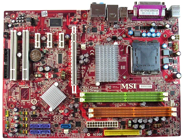
MSI P35 NEO motherboards have a fairly good layout - power connectors and ports are located mainly along the edge of the PCB. Although there are drawbacks - an FDD connector is located under the PCI slots in a not quite favorable position, and an inserted video card will interfere with opening the latches of the green RAM slots. When upgrading a computer, perhaps many users would like to have three PCI slots instead of the two existing ones, so we will also note this fact as a small drawback of MSI P35 NEO. Also not pleased with the lack of sufficiently "fashionable" currently polymer capacitors. It is worth noting that on such a PCB, MSI releases the MSI P35 Neo Combo, which supports both types of DDR2 and DDR3 memory, and the MSI G33 Neo with integrated graphics.

To cool the north bridge, a relatively large, but not very high aluminum radiator is used. The cooler on the south bridge has a much smaller size.

Since several sets of logic can be used to fill the PCB of the MSI P35 NEO motherboard, there are empty spaces for two more SATA connectors, which are installed when using the Intel ICH9R south bridge, and there is also a place reserved for the FireWire controller. In our case, the MSI P35 NEO uses the Intel ICH9 chip, which supports four SATA II ports without the possibility of creating RAID arrays. An additional Marvell 88SE6111 controller is used to ensure the operation of the IDE port and one more SATA.
For ease of connection, the eight internal USB ports and the system panel connector are color-coded.

MSI P35 NEO motherboard has only two PCI slots, three PCIE x1 and one PCIE x16 slot. Of the controllers integrated on the board, one can note the gigabit network card on RTL 8111B, eight-channel Realtek ALC888 audio codec, the front panel connector of which supports connections in HDA and AC`97 formats.

The processor power regulator for the MSI P35 NEO motherboard is only three-channel, but for a motherboard of this class this fact is not surprising.

The following ports are displayed on the rear panel: two PS / 2 for keyboard and mouse, four USB connectors, COM and LPT ports, an RJ45 connector for network connections and connectors for 8-channel audio.

The MSI P35 NEO motherboard has three fan headers, one of which is a 4-pin for the CPU cooler, and the rest, for connecting the case fans, are 3-pin. All connectors are located in different parts of the board, making it easier to choose where to connect.
MSI P35 NEO motherboard uses BIOS on AMI code with a lot of customization. Almost all overclocking settings are located in a separate section of the Cell Menu.
Settings required for overclocking:
|
Parameter |
Menu name |
Range |
|
|
Processor technology |
EIST, CPUID MaxVal, Execute Bit |
||
|
Proprietary Intelligent Overclocking Technology |
1, 3, 5, 7, 10, 15 % |
||
|
CPU multiplier |
Adjust CPU Ratio |
||
|
System bus frequency |
Adjust CPU FSB Frequency |
||
|
PCI Express bus frequency |
Adjust PCI-E Frequency |
||
|
Dividers for memory |
FSB / Memory Frequency |
1:1.25; 1:1.5; 1:1.67; 1:1.2; 1:1; 1:1.2; 1:1.6; |
|
|
Memory timings |
CAS, RAS to CAS, RAS Precharge, RAS Act to Prechar, tRFC, tWR, TWTR, TRRD, tRTP |
||
|
CPU voltage |
|||
|
Voltage on memory modules |
|||
|
FSB bus voltage |
|||
|
Northbridge tension |
1.25 - 1.65V |
||
|
I / O controller voltage |
|||
|
South bridge voltage |

The BIOS has the ability to activate proprietary D.O.T. (Dynamic Overclocking Technology), with which you can overclock the processor from 1% to 15%.

There are seven dividers to set the memory frequency, with which you can best set the frequency during overclocking.

As usual, it is possible to adjust the timings and sub-timings of the RAM, but you can notice the absence of the 1T / 2T Memory Timing setting, which changes the decoding time of commands.

Wide ranges of voltage settings will make it possible to increase system stability during overclocking. In addition, the critical value levels are shown very conveniently to help less experienced users navigate.

In the Hardware Monitor window, you can monitor:
- temperature of the processor and motherboard;
- rotational speed of the processor cooler and two case fans;
- voltage on power lines 3.3V, 5V, 12V, 5V SB and the processor core.
In the "CPU Smart FAN Target" item you can enable the function of automatic control of the rotation speed of the processor cooler.

The MSI P35 NEO motherboard was able to run with a system bus frequency of 530 MHz. Considering the wide range of settings in the BIOS, we can assume very good overclocking capabilities of processors with its help.

Testing the audio path based on the Realtek ALC888 codec
Overall Results (RightMark Audio Analyzer)
Performance testing
The following hardware was used to test the capabilities of the motherboards.
|
CPU |
Intel Core 2 Duo E6300 (LGA775, 1.86 GHz, L2 2 MB) |
|
Thermaltake Sonic Tower (CL-P0071) + Akasa AK-183-L2B 120 mm |
|
|
RAM |
2x DDR2-800 1024 MB PQI PC6400 |
|
Video card |
EVGA GeForce 8600GTS 256 MB DDR3 PCI-E |
|
HDD |
Samsung HD080HJ 80GB SATA-300 |
|
Optical drive |
ASUS DRW-1814BLT SATA |
|
Power Supply |
Chieftec CFT-500-A12S 500W 120mm fan |
|
CODEGEN M603 MidiTower, 2x 120 mm blowing / blowing fans |


MSI P35 NEO shows an excellent level of performance for a motherboard in its class.
conclusions
The MSI P35 NEO motherboard is a relatively inexpensive solution with good functionality and good overclocking potential, which, in a sense, has managed to exceed our expectations. Although overclocking enthusiasts should take into account the far from the most powerful processor power regulator. The MSI P35 NEO cost is one of the lowest among the offers on the Intel P35 chipset, while it has almost no obvious drawbacks. Perhaps, some future owners would like to see more PCI slots instead of the same PCI-E x1.
Advantages:
- support intel processors Penryn, made using 45 nm technology;
- a large number of BIOS settings required for overclocking;
- tested ability of the bus to work at 530 MHz;
- 8-channel High Difinition Audio;
- low cost for its class.
Disadvantages:
- lack of official support for DDR2-1066;
- very modest equipment;
- only two PCI slots;
- no external S / PDIF;
- no FireWire controller.
We express our gratitude to the company PF Service LLC (Dnepropetrovsk) for the motherboards provided for testing.
Article read 34866 times
| Subscribe to our channels | |||||
|
|
|
||||
Published on PS, we started researching motherboards in the lower price range, which are not perceived by most users as "overclocking" products. Compared to a similarly priced product called Biostar TP45 HP, the MSI P45 Neo-F motherboard has only one significant advantage - widespread use. When looking for the next candidate for review, it was decided to find a board that combines the same prevalence as the MSI P45 Neo-F, but is neither a direct nor an indirect competitor in terms of price for Biostar TP45 HP. After a short search, I found such a board - MSI P35 Neo.
INTRODUCING THE MOTHER'S BOARD
Introduced over a year ago, MSI P35 Neo comes in a small blue box.
advertising
The front side contains information about compatibility with processors and the supported frequency of the system bus. The reverse side provides information about the main technologies and capabilities:
On the side there is a sticker with the main characteristics:
The delivery set is typical for all MSI motherboards in the lower price category, it includes.