What is a home voltage stabilizer for? What does a voltage regulator give
In discussions of electrical circuits, the terms "voltage regulator" and "current regulator" are often used. But what's the difference between them? How do these stabilizers work? Which circuit needs an expensive voltage regulator, and where is a simple regulator sufficient? You will find answers to these questions in this article.
Consider a voltage regulator using the example of the LM7805 device. Its characteristics indicate: 5V 1.5A. This means that it is precisely the voltage that stabilizes and it is up to 5V. 1.5A is the maximum current that the stabilizer can carry. Peak current. That is, it can give 3 milliamperes, 0.5 amperes, and 1 ampere. As much current as the load requires. But not more than one and a half. This is the main difference between a voltage stabilizer and a current stabilizer.
Types of voltage stabilizers
There are only 2 main types of voltage stabilizers:
- linear
- impulse
Linear voltage regulators
For example, microcircuits BANK or , LM1117, LM350.
By the way, KREN is not an abbreviation, as many people think. This is a cut. The Soviet microcircuit-stabilizer, similar to the LM7805, had the designation KR142EN5A. Well, there is also KR1157EN12V, KR1157EN502, KR1157EN24A and a bunch of others. For brevity, the entire family of microcircuits began to be called "KREN". KR142EN5A then turns into KREN142.
Soviet stabilizer KR142EN5A. Analogue of LM7805.

Stabilizer LM7805
The most common type. Their disadvantage is that they cannot operate at a voltage lower than the declared output voltage. If it stabilizes the voltage at 5 volts, then it needs at least one and a half volts more to the input. If we apply less than 6.5 V, then the output voltage will "sink" and we will not get 5 V. Another disadvantage of linear stabilizers is strong heating under load. Actually, this is the principle of their operation - everything that is higher than the stabilized voltage simply turns into heat. If we supply 12 V to the input, then 7 will be spent on heating the case, and 5 will go to the consumer. In this case, the case heats up so much that the microcircuit will simply burn out without a radiator. All this leads to another serious drawback - a linear stabilizer should not be used in devices powered by batteries. The battery energy will be spent on heating the stabilizer. Switching stabilizers are devoid of all these disadvantages.
Switching voltage stabilizers
Pulse stabilizers - are devoid of linear disadvantages, but they are also more expensive. This is no longer just a three-pin chip. They look like a board with parts.

One of the versions of the pulse stabilizer.
Pulse stabilizers there are three types: lowering, increasing and omnivorous. The most interesting are omnivores. Regardless of the input voltage, the output will be exactly what we need. The omnivorous impulse does not care if the input voltage is lower or higher than necessary. He automatically switches to the mode of increasing or decreasing the voltage and keeps the set at the output. If the characteristics state that the stabilizer can be input from 1 to 15 volts and the output will be stable 5, then it will be so. In addition, heating pulse stabilizers so insignificant that it can be neglected in most cases. If your circuit will be powered by batteries or placed in a closed case, where strong heating of the linear stabilizer is unacceptable, use a pulse one. I use a penny tunable switching voltage regulator that I order from Aliexpress. You can buy.
Okay. What about the current stabilizer?
I won't open America if I say that current stabilizer stabilizes the current.
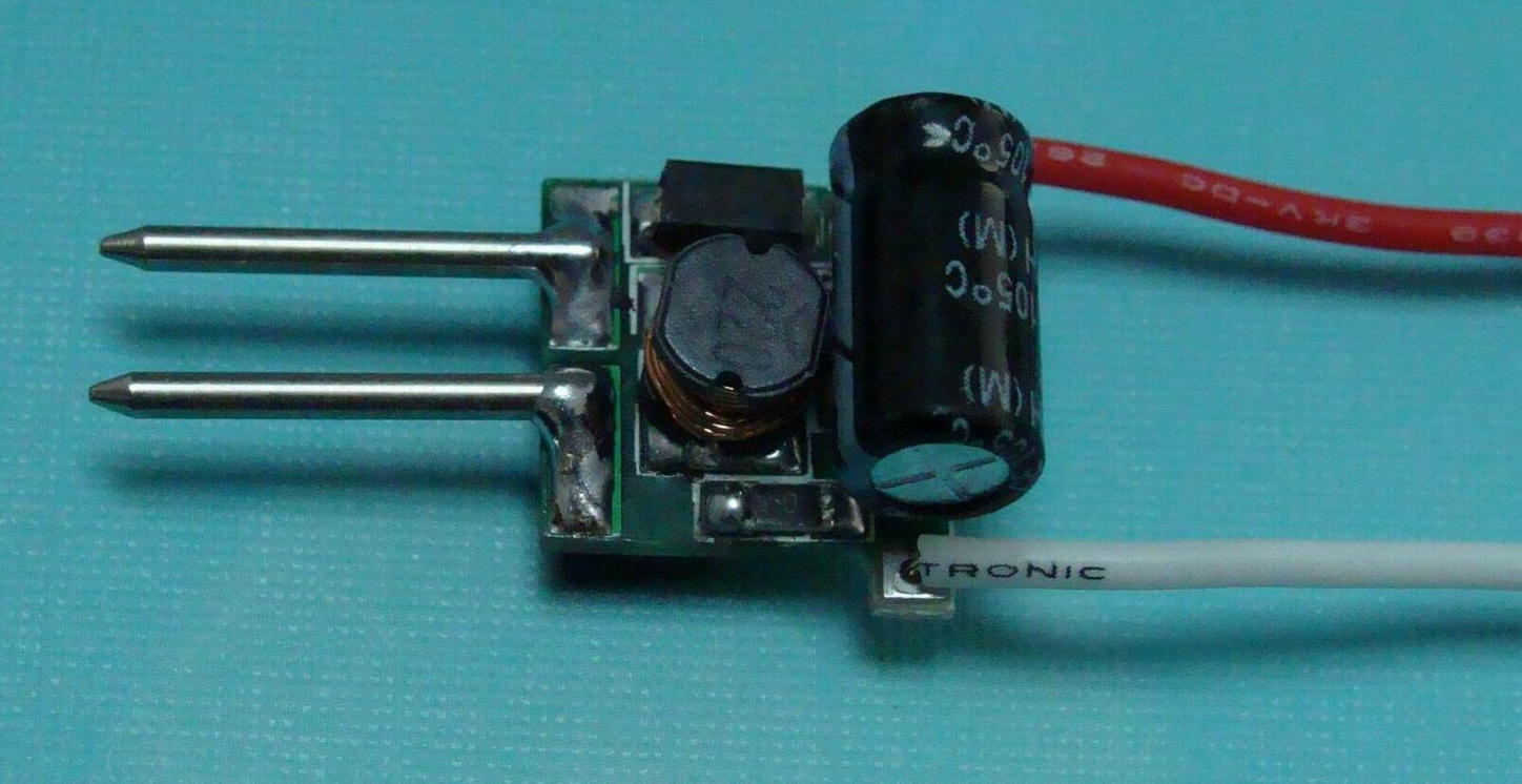
Current stabilizers are also sometimes called LED drivers. Outwardly, they look like switching voltage regulators. Although the stabilizer itself is a small microcircuit, everything else is needed to ensure the correct operation. But usually the entire circuit is called a driver at once.

This is what a current regulator looks like. The same circuit, which is the stabilizer, is circled in red. Everything else on the board is strapping.
So. The driver sets the current. Stable! If it is written that there will be a current of 350mA at the output, then it will be exactly 350mA. But the output voltage may vary depending on the voltage required by the consumer. Let's not indulge in the theory about that. how it all works. Just remember that you do not regulate the voltage, the driver will do everything for you based on the consumer.
Well, why do you need all this?
Now you know how a voltage stabilizer differs from a current stabilizer and you can navigate in their variety. Perhaps you still do not understand why these things are needed.
Example: you want to power 3 LEDs from the vehicle electrical system. As you can learn from, it is important for the LED to control the current strength. We use the most common option for connecting LEDs: 3 LEDs and a resistor are connected in series. The supply voltage is 12 volts.
With a resistor, we limit the current to the LEDs so that they do not burn out. Let the voltage drop across the LED be 3.4 volts.
After the first LED, 12-3.4 \u003d 8.6 volts remains.
We have enough for now.
On the second, another 3.4 volts will be lost, that is, 8.6-3.4 \u003d 5.2 volts will remain.
And enough for the third LED too.
And after the third, 5.2-3.4 \u003d 1.8 volts will remain.
If you want to add a fourth LED, it won't be enough.
If the supply voltage is raised to 15V, then that's enough. But then the resistor will also need to be counted. A resistor is the simplest current stabilizer (limiter). They are often placed on the same tapes and modules. It has a minus - the lower the voltage, the lower the current on the LED will be (Ohm's law, you can't argue with it). This means that if the input voltage is unstable (in cars it usually is), then you first need to stabilize the voltage, and then you can limit the current with the resistor to the required values. If we use a resistor as a current limiter where the voltage is not stable, we need to stabilize the voltage.
It is worth remembering that it makes sense to install resistors only up to a certain current strength. After a certain threshold, the resistors begin to get very hot and you have to install more powerful resistors (why the power resistor is described in this device). Heat dissipation increases, efficiency decreases.
Also called an LED driver. Often, those who are not very versed in this, the voltage regulator is simply called the LED driver, and the switching current regulator is called good LED driver. It immediately outputs a stable voltage and current. And hardly heats up. This is how it looks:
In the article we will tell you what a voltage stabilizer is, its application, how it works and its various types with schematic diagrams, and we will also help you in choosing a voltage stabilizer.
The use of voltage stabilizers has become a necessity for every home. Various types of voltage regulators are currently available with different functions and performances. Recent advances in technology, such as microprocessor chips and power electronics, have changed voltage regulators. They are now fully automatic, intelligent and equipped with many advanced features. They also have ultra-fast response to voltage fluctuations and allow their users to remotely adjust voltage requirements, including a start or shutdown function. You can look at and purchase a large selection of voltage stabilizers on Aliexpress, choose any suitable one.
What is a voltage regulator
A voltage stabilizer is an electrical device that is used to supply a constant voltage to a load at its output terminals regardless of any changes or fluctuations in the input, i.e. the incoming power.
The main purpose of a voltage stabilizer is to protect electrical or electronic devices (for example, an air conditioner, refrigerator, TV, etc.) from possible damage as a result of voltage surges or fluctuations, overvoltage or undervoltage.
Fig. 1 - Different types of voltage regulators
Voltage regulator is also known as AVR (Automatic Voltage Regulator). The use of a voltage stabilizer is not limited to home or office equipment that is powered externally. Even places that have their own internal power supplies in the form of diesel AC generators rely heavily on these AVRs for the safety of their equipment.
We can see the different types of voltage regulators available in the market. Analog and digital AVRs are available from many manufacturers. With growing competition and increased awareness of device security. These voltage stabilizers can be single-phase (220-230 volt output) or three-phase (380/400 volt output) depending on the type of application. The regulation of the desired stabilized power is carried out by the method of lowering and increasing the voltage in accordance with its internal circuit. Three-phase voltage regulators are available in two different models, i.e. balanced load models and unbalanced load models.
They are available in various ratings and ranges
KVA. The normal range voltage regulator can provide a stabilized output voltage of 200-240 volts with a gain of 20-35 volts when powered from an input voltage ranging from 180 to 270 volts. Whereas a wide range of voltage regulator can provide a stabilized voltage of 190-240 volts with a step-up resistance of 50-55 volts at an input voltage ranging from 140 to 300 volts.
They are also available for a wide range of applications such as a dedicated voltage regulator for small devices like TV, refrigerator, microwave ovens, for one huge device for all home appliances.
In addition to their main function, current voltage regulators are equipped with many useful additional functions, such as overload protection, zero voltage switching, frequency change protection, voltage cutoff display, output start and stop facility, manual or automatic start, voltage cutoff and so on. ...
Voltage stabilizers are very energy efficient devices (95-98% efficiency). They consume very little energy, which is usually 2 to 5% of the maximum load.
Why do you need voltage stabilizers and its importance
All electrical devices are designed and manufactured to operate at maximum efficiency with a typical power supply, which is known as the rated operating voltage. The operating range (with optimum efficiency) of the electrical device may be limited to ± 5%, ± 10%, or more, depending on the calculated safe operating limit.
Due to many problems, the input voltage source we receive always tends to fluctuate, resulting in an ever-changing input voltage source. This fluctuating voltage is a major contributor to the decrease in device efficiency as well as the increased failure rate.
 Figure: 2 - Problems due to voltage fluctuations
 Remember, nothing is more important to an electronic device than a filtered, protected and stable power supply. A correct and stabilized supply voltage is essential for the device to perform its functions in the most optimal way. It is a voltage regulator that ensures that the device receives the desired and stabilized voltage, no matter how strong the fluctuation. Thus, a voltage regulator is a very effective solution for those who want to get optimal performance and protect their devices from unpredictable voltage fluctuations, voltage surges and noise present in the power supply.
Like an uninterruptible power supply, voltage stabilizers are also an asset for protecting electronic equipment. Voltage fluctuations are very common no matter where you live. There can be various causes of voltage fluctuations such as electrical faults, faulty wiring, lightning, short circuits, and so on. These fluctuations can be in the form of overvoltage or undervoltage.
Repetitive Surge Effects in Home Appliances
- Permanent damage to the connected device
- Damage to winding insulation
- Interruptions in load
- Overheating of the cable or device
- The useful life of the device will deteriorate
- Hardware malfunction
- Low device efficiency
- In some cases the device may take additional hours to perform the same function
- Degrade device performance
- The device will consume more electricity, which may cause overheating
How a voltage regulator works, the principle of operation of voltage reduction and increase
The main job of the voltage regulator is to perform two essential functions: the voltage step-down and the voltage-up function. Buck and Boost function is nothing more than constant voltage overvoltage regulation. This function can be performed manually using selector switches or automatically using additional electronic circuits.

Under overvoltage conditions, the "undervoltage" function ensures the required voltage intensity reduction. Likewise, under undervoltage conditions, the "voltage boost" function increases the voltage intensity. The idea of \u200b\u200bboth functions in general is to keep the same output voltage.
Voltage stabilization involves adding or subtracting voltage from the primary power supply. To perform this function, voltage regulators use a transformer that is connected to switching relays in various required configurations. Few voltage regulators use a transformer having different taps on their windings to provide different voltage corrections, while voltage regulators (such as Servo voltage regulators) contain an automatic transformer to provide the desired correction range.
How the buck and boost function in a voltage regulator works
For a better understanding of both concepts, we will split it into separate functions.
Buck function in voltage regulator
 Figure: 4 - Schematic diagram of the step-down function in the voltage regulator
The figure above shows the connection of the transformer in the "Buck" function. In the buck function, the polarity of the secondary coil of the transformer is connected in such a way that the voltage applied to the load is the result of subtracting the voltage of the primary and secondary coils.
The voltage regulator has a switching circuit. Whenever an overvoltage is detected in the primary power supply, the load is manually connected or automatically switched to the "Down" configuration using the switches (relays).
Boost function in voltage regulator

Figure: 6 - Schematic diagram of the voltage boost function in the voltage regulator
The figure above shows the connection of the transformer in the "Boost" function. In the boost function, the polarity of the secondary winding of the transformer is connected in such a way that the voltage applied to the load is the result of the addition of the voltage of the primary and secondary windings.
How the up and down configuration works automatically
Here is an example 02 Stage Voltage Stabilizer. This voltage regulator uses 02 relays (relay 1 and relay 2) to provide a regulated AC power supply for the load in overvoltage and undervoltage conditions.

In the schematic diagram of the 02-stage voltage regulator (pictured above), Relay 1 and Relay 2 are used to provide a buck and boost configuration during various voltage fluctuation conditions, i.e. overvoltage and undervoltage. For example - suppose the AC input is 230 VAC and the required output is also constant 230 VAC. Now, if you have +/- 25 Volts buck & boost regulation, that means your voltage regulator can provide you with the constant voltage required (230 V), ranging from 205 V (undervoltage) to 255 V (overvoltage) input. AC source.
In voltage stabilizers that use tapped transformers, tap points are selected based on the amount of voltage required to be suppressed or boosted. In this case, we have different voltage ranges for selection. Whereas in voltage stabilizers that use autotransformers, servo motors are used together with sliding contacts to obtain the required amount of voltage that needs to be stabilized or increased. A sliding contact is necessary because autotransformers have only one winding.
Various types of voltage regulators
Initially, manual / voltage selector switches were introduced to the market. These types of regulators use electromechanical relays to select the desired voltage. With the development of technology, additional electronic circuits appeared and voltage stabilizers became automatic. Then came the Servo voltage regulator, which is able to stabilize the voltage continuously, without any manual intervention. IC / microcontroller based voltage regulators are now also available, which can also perform additional functions.
Voltage stabilizers can be divided into three types:
- Relay type voltage stabilizers
- Servo voltage regulators
- Static voltage stabilizers
Relay type voltage stabilizers
In relay voltage stabilizers, the voltage is regulated by switching relays. The relays are used to connect a secondary transformer in various configurations to achieve the buck and boost function.
How a relay voltage regulator works

The figure above shows how a relay-type voltage regulator looks from the inside. It has a tapped transformer, relay and electronic board. The printed circuit board contains the rectifier circuit, amplifier, microcontroller, and other auxiliary components.
The electronic boards compare the output voltage with a voltage reference. As soon as it detects any increase or decrease in the input voltage above the reference value, it switches the appropriate relay to connect the required tapping for the step up and down function.
Relay-type voltage stabilizers usually stabilize input fluctuations at ± 15% with an output accuracy of ± 5% to ± 10%.
Uses and Benefits of Relay Voltage Stabilizers
This stabilizer is mainly used for low power consumption appliances / equipment in residential / commercial / industrial applications.
- They are cheaper
- They are compact in size
Disadvantages of relay voltage stabilizers
- Their response to voltage fluctuations is slightly slower compared to other types of voltage regulators
- They are short-lived
- They are less reliable
- They are not able to withstand voltage surges, since their tolerance limit for fluctuations is less
- When the voltage is stabilized, a power path transition may cause minor power interruptions
Servo voltage regulators
In servo voltage stabilizers, voltage regulation is carried out by means of a servo motor. They are also known as servo stabilizers. These are closed systems.
How does a servo voltage regulator work?
In a closed loop system, negative feedback (also known as feed error) is guaranteed from the output so that the system can ensure that the desired result has been achieved. This is done by comparing the output and input signals. If in case the desired output is higher / lower than the required value, then an error signal will be received by the regulator of the input signal source (Output value - Input value). This regulator then generates a signal again (positive or negative, depending on the achieved output value) and feeds it to the actuators in order to bring the output value to the exact value.
Due to their closed-loop property, servo-based voltage stabilizers are used for devices / equipment that are very sensitive and need accurate input power (± 01%) to perform their intended functions.
 Figure: 10 - Internal view of the servo voltage stabilizer
The figure above shows how the voltage regulator servo looks from the inside. It has a servo motor, autotransformer, step-down and step-up transformer, motor, electronic board, and other auxiliary components.
In a servo-based voltage regulator, one end of the primary winding of a step-down and step-up transformer (tap) is connected to a fixed branch of the autotransformer, and the other end of the primary winding is connected to a movable arm that is controlled by a servo motor. One end of the secondary coil of the transformer
the buck and boost is connected to the input power supply, and the other end is connected to the output of the voltage regulator.

The electronic boards compare the output voltage with a voltage reference. As soon as it detects any increase or decrease in the input voltage above the control value, it starts working with the motor, which moves the lever on the autotransformer even further.
When you move the lever on the autotransformer, the input voltage on the primary winding of the step-down and step-up transformer will change to the required output voltage. The servo motor will continue to rotate until the difference between the reference voltage value and the regulator output becomes zero. This complete process takes place in milliseconds. Modern servo voltage regulators come with a microcontroller / microprocessor control circuit to provide intelligent user control.
Various types of servo voltage regulators
Various types of servo voltage regulators:
Single Phase Servo Voltage Stabilizers
In single-phase servo-driven voltage stabilizers, voltage stabilization is achieved using a servo motor connected to a variable transformer.
Three Phase Balanced Servo Voltage Regulators
In three-phase servo-controlled voltage stabilizers, voltage stabilization is achieved using a servo motor connected to 03 autotransformers and a common control circuit. The output of the autotransformers is varied to achieve stabilization.
Three Phase Unbalanced Servo Voltage Regulators
In three-phase single-ended voltage stabilizers with a servo drive, voltage stabilization is achieved using a servo motor connected to 03 autotransformers and 03 independent control circuits (one for each autotransformer).

Uses and Benefits of Servo Voltage Regulator
- They react quickly to voltage fluctuations
- They have high voltage stabilization accuracy
- They are very reliable
- They can withstand power surges
Disadvantages of servo voltage regulator
- They need periodic maintenance
- To clear the error, the servomotor must be aligned. Servo alignment requires skilled hands.
Static voltage stabilizers

Figure: 13 - Static voltage stabilizers
The static voltage rectifier has no moving parts like servo voltage regulators. The power electronic circuit of the converter is used to stabilize the voltage. These static voltage regulators are very accurate, and the voltage regulation is within ± 1%.
The static voltage regulator contains a step-down and step-up transformer, an insulated gate power converter (IGBT), a microcontroller, a microprocessor, and other necessary components.

How Static Voltage Regulator Works
The microcontroller / microprocessor controls the IGBT power converter to generate the required voltage level using the "pulse width modulation" method. In the Pulse Width Modulation (PWM) method, power converters in switching mode use a power semiconductor switch (such as a MOSFET) to drive the transformer to produce the desired output voltage. This generated voltage is then applied to the primary of the step-down & step-up transformer. The IGBT power converter also monitors the phase of the voltage. It can generate a voltage that can be in phase or 180 degrees out of phase with respect to the input power supply, which in turn allows it to control whether to add or subtract voltage based on the increase or decrease of the input power level.

Figure: 15 - Schematic diagram of a static voltage stabilizer
As soon as the microprocessor detects a drop in voltage level, it sends a pulse width modulation signal to the IGBT power converter. The IGBT power converter accordingly generates a voltage similar to the voltage difference by which the input power supply is reduced. This generated voltage is in phase with the input power supply. This voltage is then applied to the primary of the Buck & Boost transformer. Since the secondary coil of the Buck & Boost transformer is connected to the input power supply, the voltage induced in the secondary coil will be added to the input power supply. Therefore, the stabilized overvoltage will then be supplied to the load.
Likewise, as soon as the microprocessor detects an increase in voltage level, it sends a pulse width modulation signal to the IGBT power converter. Accordingly, the IGBT power converter generates a voltage similar to the voltage difference by which the input power supply is reduced. But this time, the generated voltage will be 180 degrees out of phase with respect to the input power supply. This voltage is then applied to the primary of the Buck & Boost transformer. Since the secondary coil of the Buck & Boost transformer is connected to the input power supply, the voltage that was induced in the secondary coil will now be subtracted from the input power supply. And therefore the stabilized undervoltage will be supplied to the load.
Uses / Benefits of Static Voltage Stabilizers
- They are very compact in size.
- They react very quickly to voltage fluctuations.
- They have a very high voltage stabilization accuracy.
- Since there is no moving part, it is almost maintenance free.
- They are very reliable.
- Their effectiveness is very high.
Disadvantages of a static voltage regulator
They are expensive compared to their counterparts.
What is the difference between a voltage regulator and a voltage regulator?
Both sound the same. They both perform the same voltage stabilization function. However, the way they do it makes a difference. The main functional difference between a voltage regulator and a voltage regulator:
A voltage regulator is a device that supplies a constant voltage to an output without any change in the input voltage. While,
A voltage regulator is a device that supplies constant voltage to an output without any change in load current.
How to Choose the Best Voltage Stabilizer for Your Home? Buying Guide
There are various factors to consider when purchasing a voltage regulator. Otherwise, you may run into a voltage regulator that may perform worse or better. Overdoing it won't hurt, but it will cost you extra dollars. So why not choose a voltage regulator that can meet your requirements and save your pocket too.
Various factors that play an important role in choosing a voltage regulator
Various factors that play a vital role and require consideration before choosing a voltage regulator:
- Required power of the device (or group of devices)
- Device type
- The level of voltage fluctuations in your area
- Voltage regulator type
- The operating range of the voltage regulator you need
- Overvoltage / undervoltage
- Stabilization / control circuit type
- Mounting type for your voltage regulator
A step-by-step guide to choosing and buying a voltage stabilizer for your home
Here are the basic steps you should follow to select the best voltage rectifier for your home:
- Check the power rating of the device for which you need a voltage regulator. The power rating is indicated on the rear of the device as a sticker or nameplate. This will be in kilowatts (KW). Typically, the rated power of the voltage regulator is indicated in kVA. Convert it to kilowatt (kW).
(KW \u003d kVA * power factor)
- Consider keeping an extra margin of 25-30% of the gimbal's rated wattage. This will give you an additional option to add any device in the future.
- Check the voltage fluctuation tolerance limit. If it suits your needs, you are ready to go ahead.
- Check the installation requirements and the size you need.
- You can ask and compare additional features in the same price range of different brands and models.
Practical example for better understanding
Let's say you need a voltage regulator for your TV. Let's assume your TV has a rated power of 1 kVA. The allowable surcharge of 30% for 1 kVA is 300 W. By adding both options, you can purchase a 1.3 kW (1300 W) voltage regulator for your TV.
The most important advice when buying a voltage regulator
Voltage stabilizers do not come from a good life, and since you have done this, then you most likely already have or have had voltage problems.
The standard voltage level, according to the norms, should be 230 volts (not 220, as many still believe).
But depending on the place of residence (length and congestion of power lines) and possible accidents in power grids (breakage of the neutral wire, overload), the voltage can be either stably understated or increased, or simply "jump" in arbitrary values.
When a small device is purchased to protect one specific device - a computer, refrigerator, TV, boiler, then there are no problems with the connection. 
The stabilizer has a plug and socket. Even a schoolboy can figure it out.
But if you want to install a powerful device to protect electrical appliances of the whole house at the same time, then you have to tinker with the connection diagram. 
What you need to connect
In addition to the stabilizer itself, you will need a number of additional materials:

The cross-section of the wire should be exactly the same as on your input cable, which comes to the switch or the main input machine. Since the entire load of the house will go through it.

This switch, unlike simple ones, has three states:
1 enabled consumer # 1 2 disabled 3 enabled consumer # 2You can also use a conventional modular automatic machine, but with this scheme, if you need to disconnect from the stabilizer, you will have to completely de-energize the whole house and throw the wires every time.
There is, of course, bypass or transit mode, but to switch to it, you need to follow a strict sequence. More on this below. 
With this switch, you completely cut off the unit in one motion, and the house remains directly with the light.

You must clearly understand that the voltage regulator is installed strictly before the electricity meter, and not after it.
Not a single power supply organization will allow you to connect differently, no matter how you prove that by doing so, in addition to the electrical equipment in the house, you want to protect the meter itself. 
The stabilizer has its own idle speed and also consumes electricity, even when operating without load (up to 30W / h and above). And this energy must be taken into account and calculated. 
The second important point is that it is highly desirable that in the circuit before the connection point of the stabilization device there is either an RCD or a diff.automatic device. 
In the method described below, just such an option will be considered. Indeed, very often these devices are hung on the wall in rooms, hallways, freely accessible for touching. 
And the breakdown of the transformer windings on the case is not such a rare thing.
Connection instructions in the dashboard
First of all, you mount a three-position switch in the switchboard, immediately after the introductory machine.

Suddenly, you have it out of order or you need to carry out any revision work. You won’t flip the wires and cut off the power to the whole apartment every time.


Choose a place to install the voltage regulator. It is also impossible to put it anywhere. There are certain rules to be followed.
Lay two VVGnG-Ls cables from the shield to this place. 
It is advisable to mark each of them and make appropriate inscriptions at both ends:
- stabilizer input

Remove the insulation from the cores and first connect the cable in the electrical panel. Connect the phase from the wire that goes to the input of the stabilizer to the output terminals of the input machine. 
Next, deal with the stabilizer-output cable. The phase conductor (let it be a white wire), connect to contact No. 2 on the three-position switch. 
Zero and ground from both cables are planted on the corresponding busbars. 
Now you need to feed the phase directly from the input machine to the three-position machine. You clean the assembly wire of the PUGV, end the conductors with NSHVI tips and start it from the phase output of the input circuit breaker to terminal 4 of the switch. 
All that remains to be done in the dashboard is to power all the machines from terminal 1 of the three-position controller. 
Do this operation again with flexible mounting wires.
Thus, according to the scheme, you applied the phase from the input automaton to the 3-position machine, and then distributed the load through its contacts, by connecting it through a stabilizer (contact No. 2-No. 1) and directly without it (contact No. 4-No. 1).
In your particular case, these contact numbers may not coincide with the numbers indicated here! Be sure to specify everything in the instructions or in the passport for the machine.
Stabilizer connection
Now we turn to the direct connection of the stabilizer itself. In order to get close to its contacts, you may need to remove the outer cover. 
Pass two cables (input and output) through the holes and clamp them under the terminals according to the following scheme:
- tighten the phase conductor of the stabilizer input cable to the INPUT (Lin) terminal
- neutral core (blue) to terminal N (Nin)
- earth conductor to screw terminal marked "earth"

By the way, there may not be a separate “ground” terminal. Then tighten this core under the screw on the body of the device itself. 
There are models with terminal blocks for only 3 wires. In them only the phase comes back. 
Zero for power supply of electrical appliances is taken from the common panel.
Now when you have applied voltage from the shield to the stabilizer, you need to return this voltage, but already stabilized, back to the general shield.
To do this, connect the cable - the output from the stabilizer.
- its phase conductor to the terminal OUTPUT (Lout)
- zero to N (Nout)
- grounding conductor, in the same place as the grounding conductor from the input cable

Visually check the entire circuit again and close the lid. 
Circuit check
The first activation must be done without load. That is, all machines except the introductory one and what goes to the stabilizer must be turned off. 
Run it idle and control the work. Input and output parameters, whether there is extraneous noise or squeak.
It also does not hurt to check the correctness and accuracy of the technical data that are displayed on the electronic board. 
If you have a 380V three-phase network at home, then for such a connection it is recommended to use 3 single-phase voltage stabilizers, each connected in a separate phase. 
More details about the advantages of three-phase and single-phase devices and when to choose which one can be found in the article ””.
Connection errors
1 Incorrect location and installation location You can have everything perfectly connected and follow the circuit, but the stabilizer will constantly warm up and turn off, or errors will pop up on its display.
 Of course, this point can hardly be called a mistake. Moreover, more than 90% of consumers do just that.
However, this switch can really save your device from failure.
The fact is that the switching of the voltage regulator from the normal mode to the "transit" mode must be performed with a certain sequence.
First you turn off the vending machines on the stub panel. 
Then move the switch itself to the TRANSIT or BYPASS position. 
And only then turn on the machines again. 
Many people forget about this and do the shift under load. Which ultimately leads to breakdowns.
With a 3-position machine, this is impossible. You automatically switch the voltage, without any manipulation on the stabilizer. And all this with one key!
You don't need to memorize any sequence. So this procedure can be safely trusted to any family member.
3 Use for connecting a cable with a smaller cross-section than the input You can only choose a smaller cross-section when you are supplying power to individual loads.
If you have the whole house on the stabilizer, then please observe the input parameters according to the entire house load.
4 Lack of lugs on stranded wires For some reason, many people forget that often the entire load of your house passes through the stabilizer. Exactly the same as on the input machine.
At the same time, in the electrical panel all the wires are crimped, even on the lighting switches with minimum currents, but on the terminal blocks of the stabilizer or its automatic machines, you can constantly find a bare wire just tightened with a screw. 
Therefore, do not skimp, and purchase the appropriate tips in advance with the device.
5 Knocks out a common machine gun in the dashboard Sometimes after connecting the stabilizer, the introductory machine begins to knock out. At the same time, without a stabilizer, everything is fine and nothing turns off.
Many people immediately sin on the wrong connection scheme or a defect in the apparatus. They take him for warranty repairs, etc.
And the reason may be quite different. If your voltage is too low 150-160V, then when it rises to the standard 220-230V, the current in the network will increase significantly. 
Hence all the problems. Pay attention to this before carrying it back to the store.
There are many types of voltage stabilizers on the market now. These are electronic and electromechanical, hybrid and thyristor. But to say that some are better and others worse will not be correct. Each of them has its own scope. It's like saying that a Kamaz truck is worse than an urban business-class Mercedes. The first has its own scope, while the second has its own and cannot be replaced with one another. Kamaz is not suitable for delivering a businessman to a meeting, and you cannot bring 10 tons of cargo in a Mercedes. But on the contrary - Kamaz can easily transport 10 tons of sand, and Mercedes will comfortably deliver a businessman to a meeting.
So it is with voltage stabilizers. For example, relay stabilizers can work quietly even at sub-zero temperatures (up to -30 ° C), but is this ability needed if they stand inside a heated house? No.
But for summer cottages, the ability of relay switches to work at temperatures below zero is very useful.
Therefore, for a private house in stabilizers, qualities such as smooth regulation (so the lights don't blink) and how much is the exact output voltage.
Voltage stabilizer for home how to choose
Continuous voltage regulation is the main feature electromechanical voltage stabilizers. Inside they have a copper winding, along which a brush drives with the help of a servo. When the voltage in the mains changes, the servo drive moves the brush along the winding, thereby smoothly equalizing the voltage. In addition, this adjustment method allows you to maintain a very high voltage accuracy at the output of the stabilizer (220V ± 3%), which is also important when used with home video and audio equipment.
But classic electromechanical stabilizers always have one very important drawback - this is a rather narrow input voltage range (up to 140V). This means that when the voltage in the power grid falls below 140 volts, the electromechanical stabilizer simply turns off and de-energizes all electrical appliances in the house.

Electromechanical stabilizer design
To eliminate this drawback, the so-called hybrid voltage stabilizers capable of equalizing voltage in the range of 105V ... 280V. They got their name due to their design features. Inside the hybrids, in fact, there are 2 modules - electromechanical and relay. The main operating mode of hybrids is electromechanical (active when the input voltage changes in the range from 140V to 280V), with smooth and high-precision alignment of all fluctuations in the power grid. But when the voltage drops below 140 volts, the protective shutdown no longer works, but instead a relay unit is connected, which is able to pull out the drawdowns to 105V.
Advantages of hybrid stabilizers:
- smooth adjustment (bulbs will not blink);
- very accurate - hold 220V (± 3%);
- equalize the voltage with 105V.
The disadvantages include:
- floor version - Cannot be hung on the wall. Although using a special rack, you can install them one above the other;
- can only work at temperatures above 0 ° С.
Comparison of characteristics of electromechanical stabilizers:
In addition to hybrid devices for the home, they also put thyristor Surge Protectors. The role of the power switch in them is played by a semiconductor element, a thyristor. Thanks to this, it is possible to further expand the range of input voltages and pull out drawdowns up to 60V!
Due to the absence of moving parts, thyristor stabilizers create absolutely no noise during operation. This makes it possible to use them even inside city apartments. In addition, thyristor devices are considered the most durable among voltage stabilizers. Because of this, manufacturers often give them an extended warranty.
The advantages of thyristor stabilizers:
- cope even with abnormal voltage drops up to 60V;
- absolutely silent (noise level - 0dB);
- adjustment is carried out smoothly;
- high-precision - at the output we get 220V ± 5% (and 220 ± 3% for frost-resistant modifications)
- high response speed (20ms);
- made in a hinged version (do not take up much space and are conveniently mounted on the wall);
- have an extended warranty for 3 years.
disadvantages
- the production technology of thyristor stabilizers is quite expensive, so the price tag of the devices does not allow them to be installed in every home.
Comparison of characteristics of thyristor models:
First rule:
For the house, you need to install a voltage stabilizer with smooth adjustment (so that the lights do not blink). These requirements are met: electromechanical (hybrid) or thyristor stabilizers.
Step # 2 - Single Phase or Three Phase?
So, we have decided on the type of stabilizer - we need an electromechanical / hybrid or thyristor device.
Now you need to understand whether to put single-phase (at 220V) or three-phase (at 380V)?
There are two options:
- if one phase is connected to the house, then we select a single-phase stabilizer;
- it would seem that for a three-phase network there should be the same logical conclusion - for three phases, take a three-phase unit. But there is one caveat.
All three-phase stabilizers are designed in such a way that when one of the phases disappears, protection is triggered in the stabilizer and it turns off, de-energizing the entire house. Therefore, only if there are three-phase consumers in the house, we install a three-phase stabilizer.
If the consumers are only 220V, then it is better to put 3 single-phase voltage stabilizers (one for each phase). Most often, such a solution will even be cheaper in money.
What if you don't know how many phases are connected to the house?
The most common answer to this question is: "If you had three phases, you would know about it." Indeed, most of the old-built private houses have one phase and all household consumers are designed for 220V (TV, refrigerator, computer, video and audio equipment).
Three phases are often brought to modern country cottages. in addition to household electrical appliances, it is planned to install three-phase consumers at 380V.

2 or 3 wires are connected to the house - a single-phase network, 4 or more - three-phase.
Second rule:
If one phase is connected to the house, we stop at single-phase stabilizers.
For a three-phase network:
- if there are 380V consumers - we put one three-phase stabilizer;
- if the consumers are only 220V, we put 3 single-phase stabilizers (one for each phase).
Step # 3 - Should it work in sub-zero temperatures?

So, now we know that depending on the consumers, you need to install a single-phase or three-phase device.
The next step is simple - will the stabilizer be in the heated room or not. Most often, the device is located in a technical room inside the house and there is no need for frost-resistant devices.
If suddenly it is necessary to work at temperatures below zero, then we remember this parameter in the stabilizer as important.
Third rule:
Most often, stabilizers are installed inside the house and there are no requirements for frost resistance. But if it stands in an unheated room, then we choose among stabilizers that can work at sub-zero temperatures.
Step # 4 - How much power do you need a stabilizer?
At the previous stages, we learned that a house needs a device with smooth adjustment, decided on the number of phases of the required device (single-phase or three-phase) and decided for ourselves whether it will stand in a heated room or a frost-resistant version is needed.
Now you need to understand how much power the device should have.
magazin energia ru
This issue must be carefully considered, since taking a stabilizer of low power, as a result, we will get frequent shutdowns of the stabilizer due to overload.
The basic rule that is usually followed when choosing a voltage stabilizer for a home is as follows:
For each private house or country cottage, an introductory machine is installed, which does not allow loading the electrical wiring of the house more than it is designed. This is not due to the "greed" of electricians, as if they do not want to allow the owner of the house to turn on appliances with more power than allowed. The reason is trivial - to prevent a fire from occurring. In order to prevent overheating of the wires and the occurrence of a fire due to this, an introductory machine is installed. If a person tries to simultaneously load the electrical wiring with devices of greater power than allowed, the input circuit breaker will perform a protective shutdown and prevent a fire in the house.
Most often, such introductory machines are placed on the house:

Introductory machine for 40 A (ampere)
In order to find out what power a voltage stabilizer is needed for our house, the same formula is always used:
- Option number 1 - a single-phase 220V network is connected to the house
In this case, we multiply the value of the input machine (we have it 40 amperes) by 220 volts:
40 * 220 = 8 800
It turns out that our house needs a stabilizer with a capacity of no less than 8800 VA (volt-ampere) or 8.8 kVA (kilovolt-ampere).Knowing the typical power range of stabilizers:
5, 8, 10, 15, 20, 30 kVAWe understand that a stabilizer for 8 kVA will no longer cope with our load, but for 10 kVA it will be it.
- Option number 2 - a three-phase 380V network is connected to the house
In the case of a three-phase network, the solution is as follows:- if there are 380V consumers at home - we put one three-phase stabilizer.
Its power is calculated as follows:
An introductory machine for private houses with a three-phase connection, most often 20 amperes.
We multiply 20 amperes by 200V and multiply the resulting figure by 3 more:
20 * 220 * 3 = 13 200
It turns out that a three-phase stabilizer with a capacity of at least 13200 VA (volt-ampere) or 13.2 kVA is needed for the house. (kilovolt-ampere).
Again, taking into account the power range of three-phase stabilizers (9, 15, 20, 30 kVA), we understand that we need a 15 kVA stabilizer.
In total, you need a 15 kVA three-phase unit. - If 3 phases are connected to the house, and all electrical appliances are ordinary, designed for 220V and it is not planned to install three-phase consumers, then it will be more efficient to install three single-phase stabilizers (one for each phase). This is done for the reason that in the event of a voltage failure in one of the phases, the three-phase stabilizer will de-energize the entire house. When installing three single-phase stabilizers, this problem does not arise and electrical appliances continue to work on the remaining two phases.
The power is calculated as for a conventional single-phase stabilizer (described above) with the difference that not one but three pieces are needed:
40 * 220 = 8 800
In total, you need 3 stabilizers of 10 kVA each.
- if there are 380V consumers at home - we put one three-phase stabilizer.
Fourth rule:
Depending on the number of connected phases:
- for a single-phase network (220V), a single-phase 10 kVA stabilizer is most often installed;
- for a three-phase network, either one three-phase stabilizer of 15 kVA or three single-phase of 10 kVA are installed (one for each phase).
magazin energia ru
Step # 5 - How much does the voltage drop?
In the previous 4 steps, we found out that a stabilizer with smooth and precise regulation is required for the house (electromechanical / hybrid or thyristor devices are suitable for this). We learned that with a single-phase network, a single-phase stabilizer is needed, and with a three-phase network, one three-phase or three single-phase (in which cases and which one is indicated in Step # 2). At Step # 3, we decided whether we need a frost-resistant device or whether it will stand inside the house, in a heated room. And at Step 4 we calculated the required power of the device.
And now we come to that small, but very important point, which 80% of people forget about when choosing a stabilizer.
In theory, everything is simple - I looked at the figure on the introductory machine, multiplied it by 220V, and a stabilizer is needed for such a power. But for some reason they forget that when the voltage drops (when the outlet is not 220V, but already 170V, 140V and below), the power that any stabilizer can produce also drops. And instead of the declared 10 kW (kilowatts), it already produces 8 or 7 kW. Thus, if the home network is fully loaded (electrical appliances with a total power of 10 kW are turned on and operating at the same time), then the stabilizer will not be able to provide them with this power and, in order to avoid overheating and failure, protection will work, which will turn off both the stabilizer and all electrical appliances in the house.

Dependence of the output power of the stabilizer on the voltage drop in the mains.
As you can see from the graph above, when the voltage drops to 170V, the stabilizer will be able to deliver a maximum of 85% of its power. If we take, for example, a 10 kW device, we get:
10 * 85/100 \u003d 8.5 kW total
With a voltage of 140V, we have 65% of the power:
10 * 65/100 \u003d only 6.5 kW
If our drawdowns reach 110V, then at the output you can count on only 40% of the power, and this is:
10 * 40/100 \u003d 4 kW total
It is for this reason that all electricians unanimously advise taking a voltage stabilizer with a power reserve of at least 30%.
The situation with increased voltage is not so common, but the power reserve must be taken in this case:

Dependence of the output power of the stabilizer at increased voltage.
Already at 255V, the stabilizer begins to lose power, and at 275V it is capable of delivering only 80% of the declared values. A protective shutdown occurs at 280V.
Fifth rule:
With a low or high voltage, the power of any stabilizers drops. Therefore, you should always take a stabilizer "with a margin" in power (at least 30%).
Conclusions:
So, today we learned that for the house:
- only accurate stabilizers with a small error at the output and smooth regulation are suitable. This is necessary so that at the time of voltage equalization the bulbs do not blink and the electronics in the house work normally. Electromechanical, hybrid or thyristor devices are suitable for these requirements;
- decided whether you need a single-phase or three-phase device;
- found out for themselves whether it will stand in a heated room or a frost-resistant device is required;
- learned that for houses with one phase supplied (220V), they most often take a 10 kVA (kilovolt-ampere) stabilizer, and for a three-phase network (380V), 15 kW (kilowatt) devices are chosen. And they learned to calculate the power of the required stabilizer individually for their home;
- remember that the stabilizer must be taken with a power reserve (at least 30%).
I hope we were able to help as much as possible with the selection of a stabilizer for the home. If you have learned something new for yourself and find this information useful, click on the social media buttons below and save this article to yourself so as not to lose.
One of their characteristic features of modern power systems are voltage fluctuations, which can be not only smooth, but also flow in the form of sharp surges. Such situations arise under the influence of a number of factors associated primarily with an increase in the number of consumers, significant wear and tear of cable lines, etc. Voltage can drop significantly, especially during peak periods.
It is quite possible to avoid such negative phenomena by installing a voltage regulator. Thus, it is possible to save a large number of electronic boards and other sensitive elements used in modern household appliances and equipment.
How the stabilizer works
The basic principle of operation of stabilizing devices is the use of transformers in their circuits with parameters that can be changed and corrected. They belong to electromagnetic devices, the main purpose of which is to change the characteristics of alternating current and voltage within specified limits.
The simplest design of a transformer with two coils or windings wound around it, independent of each other. An alternating current is supplied to the primary coil, and the load is connected to the secondary. In this place, an electric current also occurs, but with different parameters. A similar state is called. Voltage stabilizers use more complex transformer designs where the coils are connected.

A voltage stabilizer consists of several main parts:
- A monitoring device that monitors the input voltage and its parameters. From here all information goes to the control system.
- Control element with a moving part and servo drive. After energizing, it begins to move, switching connections between the taps of the transformers. As a result, the current parameters also change. In electronic systems, control elements are installed that provide direct switching of the windings.
- A part with which a continuous supply of power and protection against excessive loads and short circuits is carried out. As a rule, these are thermal and magnetic releases. There is also additional protection installed against short-term exposure to high-voltage impulses.
The need for a stabilizer at home
What is a voltage regulator for? Stabilizing devices are connected together with all devices to a common electrical network. Their main task is to maintain the output voltage within specified limits, despite significant fluctuations in its parameters at the input. Stabilizers can be installed at the input, equalizing the supplied power. In case of any deviations from the norm, they completely cut off the voltage supply or block the power of individual devices.
Therefore, before finally deciding whether a voltage stabilizer is needed in an apartment, it is recommended to measure the voltage of the home network at different times of the day. This procedure should be carried out as long as possible to obtain the most complete information. Regulatory documents require that the average values \u200b\u200bbe in the range of 220-240 volts, and in Russia, a breakdown from 198 to 253 volts is allowed.

As practice shows, most are supplied with high-quality power supply that meets generally accepted standards. However, if the measurements taken have revealed deviations from the norms for a long time, it is worth considering using a stabilizer. This will primarily protect household appliances that are highly sensitive to low-quality electricity.
Voltage stabilization is required for air conditioners and vacuum cleaners equipped with high-power asynchronous motors. With a reduced voltage, they may be heated up strongly and subsequently fail. The same goes for old TVs and refrigerators, which start to overheat and buzz when the voltage drops. Incandescent lamps stop working normally and do not produce the required brightness. Reduced voltage will adversely affect the function of microwave ovens. The radiation power decreases, and in the event of a sharp drop in parameters, the device stops working altogether.
Voltage surges have a negative effect on the functions of washing machines, dishwashers, electric stoves and water heaters. That is, the question of why a voltage regulator is needed is resolved by itself. Therefore, in order to effectively solve the problem of poor-quality power supply, it is necessary to choose the most suitable stabilizing device.
The main types of stabilizing devices
All stabilizers differ in design and type of execution, purpose and principle of operation. In accordance with this, they are conventionally divided into categories.
Electromechanical
Their work is based on the simplest principles. The varying input voltage acts on the graphite brushes, which begin to move along the transformer winding. In the same way, the output voltage changes. The earliest models were equipped with a special switch with which the brushes could be moved manually. At the same time, the voltmeter was monitored so that its arrow was set in the desired position.

In modern devices, all regulation processes are fully automated. For this purpose, small electric motors are used that move the brushes with a varying input voltage. That is, they have all the necessary properties.
The undoubted advantages include the high efficiency of these devices, their simple design and reliable operation. The main disadvantage is the low speed of response to changing input parameters and the rapid wear of mechanical parts. Therefore, these stabilizers require regular maintenance.
Electronic
They are distinguished by the complete automation of all inherent processes. Triacs or thyristors are used to switch between windings. The state of the input voltage is monitored by a microprocessor.

When the current parameters change, a command is issued, after which one stage closes and the other opens. This allows you to accurately adjust the number of transformer turns involved in stabilizing the output voltage.
Electronic devices are characterized by good performance, low noise and small size. The main disadvantage is considered to be weak resistance to stress.
Ferroresonant
The operation of these devices is based on the magnetic effect on the transformer cores made of ferromagnets. They have a fairly high power rating and are equipped with special filters that reduce electromagnetic interference.

Distinctive features are high speed, control accuracy and long service life. In domestic conditions, such stabilizers are used very rarely, since they emit a continuous hum during operation.
The disadvantages include large dimensions and high cost.
How to choose
In most cases, the owners of apartments and private houses choose relay-type devices. They have a high switching speed, are reliable in operation and successfully compete with electronic devices.
The choice of stabilizers is carried out according to certain criteria.
Power
It is selected taking into account the parameters and technical characteristics of household devices and equipment that are planned to be connected through a stabilizer.
The power is calculated as follows. First, it is necessary to establish the total amount of consumer denominations based on passport data. After that, the device with the maximum starting power is determined. Next, the difference between the rating and the starting power is established. The resulting value is added to the sum of the denominations set at the very beginning.

Number of phases
Single-phase stabilizers are used in apartments and most private houses. Three-phase devices are installed together with three-phase consumers or, if the entire facility is connected to an appropriate three-phase network.
Such a voltage stabilizer for a home is quite expensive, so it is more economical to use three separate single-phase stabilizers.

Range
It can be working or marginal. In the first case, a possible input voltage is set, according to which the output will be 220 volts in single-phase networks and 380 volts in three-phase networks. These values \u200b\u200bare conditional, with acceptable errors.
In the second case, the voltage deviation at the input and its difference with normal indicators are determined. When the standard value is exceeded, the devices are turned off, but the voltage stabilizer itself in the house remains in working order.

Accuracy
It consists in the maximum value of the permissible voltage deviation from the norm. For some inexpensive model, this figure is 2-7%, and expensive devices are more accurate with a deviation of no more than 1%.
Installing stabilizers is not particularly difficult. Most of these devices can be easily installed by yourself and attached to the brackets included in the kit. The only technical requirement is the distance to the ceiling, which should not be less than 30 cm.
Related entries:
 How to set up my tele2 unlimited
 The computer does not see the USB flash drive - the reasons and solutions to the problem
 How to connect the Internet for a day from Tele2?
 What to do if the computer does not see the USB flash drive in Windows
 The computer does not see the USB flash drive, what to do


