Electric train ER9M, ER9P. Electric circuits of electric trains ED9T and ED9M Overall dimensions of the motor carriage ed9m
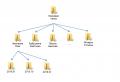
The location of the controls of the ED9M electric train is shown in Figure 1.3. Figure 1.4 shows the location of the controls on the console and on the rear wall of the ED9T electric train cab. The control panel in the driver's cab is made of separate blocks, in each of which the devices are arranged according to their purpose. Compound electrical circuits blocks with a train diagram are carried out with plug connectors of the ShR type installed on block Ш, located under the control panel in the middle part. There is also block P, on which resistors of semiconductor-switching lamps are installed, to ensure noise immunity. The driver's controller 1 KU.04O with a reversible handle is installed in front of the driver on the console. To the left of the controller is block K with the main switches for controlling the movement of the train. On the K block there are switches: to turn on the power of the doors, to control the pantograph, "Release the brakes", "Restore protection", "Disable explosives", "Sandboxes", traction (CT), "Start SIO" (SSZ-I systems), as well as toggle switches for switching on lighting and cockpit. To the right of the controller is block A, on which the ALSN control equipment is located (the vigilance button, the "KP" button for checking the ALSN, the "DZ" switch for setting the time between pressing the vigilance button in areas without automatic blocking). Above block A is block D with toggle switches for automatic doors. The doors can be operated by the driver or assistant. For this, in addition to switches in unit D, units DV are installed in the working vestibule on the frames of cabinets No. 0 and No. 1.
Head car

Figure: 1.3. Controls and equipment of the driver's cabin of the ED9M series electric train:
1 - display unit BIL-2M; 2 - radio station; 3 - microtelephone handset; 4 - electric heater; 5 - driver's crane; 6 - RB button; 7 - switch for the brightness of the spotlight; 8 - whistle and typhon control pedal; 9 - driver's vigilance control pedal; 10 - driver's controller; 11 - block of control panel switches; 12 - 220 V socket; 13 - 110 V socket; 14 - hand brake steering wheel; 15 - additional radio station control panel; 16 - plafond for illumination of the driver's assistant's workplace; 17 - traffic light for automatic locomotive signaling; 18 - radio station loudspeaker; 19 - block of signal lamps; 20 - kilo-voltmeter; 21 - brake line and surge tank manometer; 22 - pressure gauge of the brake cylinder and pressure line; 23 - switches for automatic doors
Chapter 1. General information

Figure: 1.4. Arrangement of controls for electric train sernn ED9T: ■
a - control panel; b - control unit on the rear wall of the cab; 1 - searchlight switch; 2 - RB button; 3 - reverse; 4 - driver's controller; 5 - traction switch button (CT); 6 - sandbox switch; 7 - block of switches for pantograph control, cabin lighting, brake release and protection restoration; 8 - block of switches for door control and high-voltage switch disconnection; 9 - block for changing the setting of the starting current of the acceleration relay; 10 - block of switches; II - block of signal lamps; 12 - kilovoltmeter; 13 - pressure gauge of the brake line and equalizing cylinder; 14 - pressure gauge of the brake cylinder and pressure line; 15 - block "B"
Above block K is block L, on which sixteen internal alarm lamps are installed, as well as a block for smoothly changing the setting of the starting current of the acceleration relay (1 B.712) and a button for turning on the windscreen washer. On the rear wall of the cab, behind the driver's seat, there is block B for controlling the auxiliary train systems. On block B are installed: block T with thermostats that maintain the set temperature in the cabin, control switches
cab ventilation and heating, heated windows and side mirrors, interior lighting, signals and buffer lamps, auxiliary compressor, radio communication and windshield wipers.
Between the D and L units there is a kilovoltmeter, which shows the voltage in the contact network, a two-pointer manometer for monitoring the pressure in the brake cylinder and a surge tank, and a second two-pointer mano-
meter for monitoring the pressure in the brake and pressure lines. On the right, in front of the driver's crane, a speedometer is installed on the console. Above the control panel, on the central pillar of the frontal windows, there is a locomotive traffic light, and above it is a radio station loudspeaker. There are two types of communication on electric trains - radio communication and a warning system. For negotiations with the train dispatcher, the station attendant, the drivers of other trains, the

Figure: 1.4. (continued)
two radio station control panels with handsets have been updated: for the driver - to the right of the driver's crane, for the assistant - on the left side of the control panel. The OET system is used to alert passengers and conduct business negotiations between the driver and the conductor of the tail car. In the middle part of the console, to the left of the controller, there is a console with a portable microphone for the TON system manipulator, two more microphones are in the service vestibule. Two loudspeakers of the TON system are located on the cab ceiling. On the left side of the remote control, to the left of the radio station, there is a handbrake flywheel.
There are doors above the control panel for access to the spotlight and route signs.
Under the control panel in front of the driver's seat there is a vigilance pedal and a pedal for turning on the typhon and whistle.
On the right and left of the cab walls, additional cab heating furnaces are installed.
The cabin is illuminated by two ceiling-mounted lamps. The lamps are switched on with a toggle switch located on block K. On the rear wall of the cab, behind the driver's seat, there are green lamps. The green light switch is located on block B. In addition, there is a separate lighting for the route schedule located on block D, and illumination of the assistant driver's workplace.
On the rear wall of the cab, behind the driver's seat, there is a cabinet
for clothes. Next to block B there is a cabinet for a first aid kit and a cabinet for thermoses and food. Between these cabinets there are doors for access to the thermo-fire contactors and the power switch for the burglar alarm, and below them for access to the heater chamber. All boxes and cabinets with high-voltage equipment are equipped with interlock switches, and the doors of the cab and the doors of the passenger compartment are equipped with burglar alarms.
On the roof of the car there are radio station antennas (beam and discone) and a block of searchlight resistors.
On the rear end wall of the car there are sockets and plugs for intercar electrical connections. On the front wall of the car there is a niche with doors for two control circuit sockets

Electric trains of the ED9M, ED9T, ER9P series

Figure: 1.6. Arrangement of equipment in cabinet No. 1 of the head carriage of the ED9T electric train:
Battery - battery switch; PR7 - fuse in the emergency lighting circuit and lighting of attics and toilets; Pr20 - fuse in the chain of duty lights; Pr34 - fuse in the battery circuit; Pr9 - fuse in the EPT circuit; PrZZ - fuse in the short circuit circuit; Pr14, Pr15 - fuses in the battery power supply circuit; Pr38 - fuse in the toilet heating circuit; Pr48 - fuse in the radio signaling circuit; Pr55 - fuse in the windshield heating circuit
inter-car connections that allow connecting head cars with each other.
On the frame under the car body are suspended: a box (see Fig. 1.5) with a storage battery, an electric compressor, unit 1BA. 174.2 (thermal sensor of the charging unit), transformer 1TP.071.1 (power supply NOV for battery charging), choke 1DR.007.1 for smoothing pulsations in NOV circuits, electric air distributor, air distributor, control unit for aerosol fire extinguishing installation BU UAP, three air tanks with a volume of 170 liters, air tank with a volume of 55 l, an equalizing tank with a volume
volume of 20 liters, an auxiliary tank with a volume of 16 liters, an oil separator, a heater for the waste pipe, two dump valves, two signaling devices for brake release, two whistles, two typhons, a shut-off valve VVZISH. There are brake cylinders on the bogie frames. On the left and right sides, under the car body, water supply pipes are installed, which are used for mechanized cleaning of the car.
In the cab, behind the driver's seat, there is a cab cabinet, in the upper part of which there is block B, and in the lower part there is an EPK-150I electro-pneumatic hitchhiking valve, a double crane
thrust regulator, AK-11B pressure regulator, a valve for replacing electro-pneumatic braking with pneumatic braking, two isolation valves, a filter, a tone calling device (TVU), a preliminary light signaling unit (BPSS), a fuse block for protecting train wires (switching on an auxiliary compressor, heating, power supply SSZN-I-1B.711) and fuse panel PP1.
Cabinet number 0 stores inter-train connections. The electric train can be equipped with security systems: CLUB, KPD-ZV, USAVP / 2, SAUT-TsM / 485. Therein
Chapter 1. General information

Figure: 1.7. Location of equipment in cabinet No. 2 of the head carriage of ED9T electric train:
DUKS - discrete slip control device; RO - brake release relay; RPT - pneumatic brake relay; RT - brake relay; RKB - safety control relay; PTV-4 - intermediate relay of the car thermoautomatics; RKO - brake release control relay; RKT - brake control relay; RN V-3 - fan voltage relay No. 3; KV-3 - fan contactor No. 3; РЗ - protection relay; Pr50, Pr51, Pr52 - fuses in the cab heating circuit
in this case, the KPD-ZV system units are installed in cabinet No. 0.
Cabinet No. 1 contains a unit (1BA. 169.2) with 50 V, PO V power supplies, battery charge, security alarm circuits, ammeter and voltmeter for battery charge, 220 V power supplies, wire insulation integrity control, battery charge packet switch. On the side wall of the cabinet there are switches for lighting the service vestibule and burglar alarm. On the ceiling of the cabinet there are fire-prevention temocon-tactrators.
Cabinet No. 2 contains: block (1 B.691) of equipment for interfacing ALSN with the train circuit; block (1B.699) with control equipment for heating and ventilation of the cabin, electropneumatics; radio station power filter; PPU electronic unit; power supply unit for windshield wipers and glass heaters BP-01; device for monitoring and transmitting notifications of the SSZ-I PKPI-P, EB PPU system.
Cabinet No. 3 contains: a low-frequency amplifier U-100, an adapter of the TON equipment set, a cabinet with radio equipment from the radio set, a connection device and an intercom and switching device (PKU) of the communication equipment "S-
drove ", a locomotive filter FL 25/75, a set of ALSN V-1D equipment, a locomotive power supply 110IP-LE.
On the doors of cabinets No. 2 and No. 3 there are consoles for connecting manipulators of the TON system.
Cabinet 4 contains a panel (1PA441) with control equipment: interior ventilation and heating, compressor, lighting, electropneumatics.
A panel (1PA-383) with high-voltage control circuit equipment is installed in cabinet No. 5.
The location of the equipment in the cabinets of the head carriage of the ED9T electric train is shown in Figures 1.6 and 1.7.
FOREWORD
The book contains general information about electric trains alternating current ED9M, ED9T and ER9P. The issues of their formation, devices, operation of electrical circuits and some malfunctions of electrical equipment are considered.
The manual is compiled on the basis of an electric train of the ED9M series produced by the Demikhovsky Machine-Building Plant, with an indication of the differences from electric trains of other series and indices and a description of their individual main units.
The manual is intended primarily for use by locomotive crews of electric trains, as well as by repair personnel of multiple-unit depots. The manual will also be useful for students of technical schools, lyceums and universities with a railway specialization.
This manual is not an educational publication and can only be used as an introductory material with general information about alternating current electric trains.
Unlike previous editions, this manual has been supplemented color illustrations of the described devices.
In connection with the constant work to improve electric trains, aimed at increasing their reliability and traffic safety, minor changes may be made to the design of electric trains that are not reflected in this publication. These changes will be reflected in subsequent editions.
Below are three illustrations from the book for example (in the book itself, the resolution is, of course, better):


CHAPTER 1. GENERAL INFORMATION
Formation of electric trains
Arrangement of equipment in wagons
Head car of the ED9M and ED9T series
ER9P series head car
Motor car of ED9M and ED9T series
ER9P series motor car
Trailer wagon series ED9M and ED9T
ER9P trailed car
CHAPTER 2. ELECTRICAL EQUIPMENT
Pantograph. Design and principle of operation
Air switch. Purpose and technical data. Design
Compressor electric motor conv. No. 548A. Appointment. Device and principle of operation
Auxiliary compressor motors. Appointment and specifications
Transformer ITP.071.1
Traction motors. Features of the device
Phase splitter. Appointment
Driver controller
Power controllers. Appointment
Reversing switch
Pneumatic contactor 1 KP.006
Purpose and principle of operation
Pantograph valve KLP-101
Pneumatic devices
Current sensors DT-010, DT-011. Purpose of current sensors
KF resistor element. Purpose and device
Start-up resistors. Purpose and device
Excitation attenuation resistor. Purpose and device
Ballast resistor. Purpose and device
Radio interference protection device (inductive-capacitive filter) FSE-ZB-3. Purpose and device. Operating principle
Rechargeable batteries... Features of the device. Service in operation
Contactors MK1 and MK2
Cam contactors.
Cam contactors K32A
Cam contactor KE-153
Relay
Electrothermal current relays (TRTP). Purpose and principle of operation
Automatic switches. Purpose and principle of operation
Fuses. Appointment
Sliding relay (1P.008). Purpose and principle of operation
Time relay P.017
Control and protection relays
Intermediate relays and time relays
Electric low-voltage interlocking. Purpose and features of the device
Thermal contact with fusible alloy. Purpose and principle of operation
Pneumatic switches
Purpose and features of the device
Switching devices. Appointment. Device and principle of operation
Communication devices
Radio station
Locomotive speed meter ZSL2M-150. Appointment. Device
Electric ovens and heating elements
Heating system of cars
Water trap heater
CHAPTER 3. ELECTRICAL DIAGRAM OF THE ELECTRICAL TRAIN
Low voltage circuits
1. Wires and their purpose
2. Settings of electronic units
3. Description of the circuit operation
4. Impact of protective devices
High voltage circuits
Low voltage control circuit supply winding
High voltage heating circuits supply winding
Power supply winding
CHAPTER 4. MECHANICAL EQUIPMENT
Wagon bodies. Features of the device
Ventilation and heating of the driver's cab of electric trains of ED9M and ED9T series
Electric heating of windshield and side windows of electric trains of the ED9M and ED9T series
Ventilation and heating of passenger spaces
Cooling system for traction motors and phase splitters
Carts
General design features of bogies of motor and trailed cars
Trolley frames
Suspension
Pivot knot
Hydraulic vibration damper (damper)
Axle box
Wheelsets
Traction motor suspension. Purpose and features of the device
Traction drive. Features of the device
Auto coupler and draft gear
Purpose and features of the automatic coupler device. Operating principle
Absorption apparatus
CHAPTER 5. PNEUMATIC EQUIPMENT
Electric train pneumatic diagram
Braking equipment
Compressors
Air diffusers
Driver's crane conv. No. 395M-5-01
Reducer conv. No. 348
Pressure switch conv. No. 404
Electro-pneumatic auto-stop valve conv. No. 150I-1
Automatic regulator of the stroke of a rod of a brake cylinder 102.40.10.001
Lever automatic adjuster type 536M
Air line fittings
Brake linkage and handbrake
Experimental ten-car electric train ED9T-0001 was manufactured by OJSC “Demikhovsky machine-building plant” (OJSC “DMZ”) in September 1995. Electric equipment of SJSC “Riga Electric Machine-Building Plant” (SJSC “REZ”), AO “Estel Pluss” (St. Tallinn), Zaporozhye Transformer Plant. The technical documentation for the electric train was developed by the department of the chief designer of OJSC “DMZ”.
Electric train ED9T-0001.
Photo: Oleg Nazarov, 1995
Electric trains ED9T and ER9T produced by SJSC "Riga Carriage Works" are practically identical in mechanical and electrical parts. The new train does not have a PVKT system (axial equalization of traction coefficients). At the same time, the following new technical solutions, systems and equipment were applied on the ED9T electric train:
The main feature of the ED9T-0001 electric train is the use new system regulation in the mode of rheostat braking. In this system, in braking mode, the TD armatures are connected in two circuits. The braking controller switches the resistors and provides seven steps of rheostat braking. At the 12th position, the electro-pneumatic braking is activated.
The TD excitation in the braking mode is performed from section 0 - 4 of the traction winding of the power transformer through a semi-controllable bridge, which allows regulating the TD excitation current.
The driver's controller (KM) has four braking positions. In the first and second positions, rheostatic braking with reduced effort is carried out. In the third position of the KM, rheostat braking is carried out with a normal setting. In the fourth position of KM, electric braking of motor cars is supplemented by electro-pneumatic braking of trailed and head cars.
The rheostat braking control system SURT regulates the currents of the TD armatures in the rheostat braking mode at different values \u200b\u200bof the braking resistor stages and maintains the TD excitation current constant when the set value is reached.
The electric train scheme provides for three stages of protection during skidding and skidding: discrete wheelset slip control devices; skewing relays (RB), responding to the voltage difference across the TD collectors; relay boxing relay (RRB), turning off the traction and electric braking modes when the voltage difference across the TD collectors exceeds 706 ± 50 V.
Discrete wheelset slip control devices (DUKS) are installed on all electric train cars. One set includes four axial speed pulse transducers mounted on all axles of the car, a logic block and four electro-pneumatic dump valves connected to the brake cylinders.
In October-November 1995, after a control run of 5,000 km without passengers at the Gorky-Moskovsky depot on the Gorkovskaya road, on the experimental ring of VNIIZhT, acceptance traction and energy tests were carried out, the purpose of which was to determine the main indicators of the electric train and assess their compliance with regulatory and technical documents operability and efficiency of its electrical systems in design and emergency modes of movement, testing of protection systems for traction electrical equipment in emergency modes. The tests included:
In mid-December 1995, the electric train was put into operation at the Irkutsk-Sortirovochny depot of the East Siberian road.
The set of electrical equipment developed for ED9T was also supplied by RER JSC to RVZ for installation on ER9TM electric trains. Until now, these electric trains have been supplied only to Belarus.