Hc 06 bluetooth connection. What is a bluetooth module? Connecting from a smartphone using Bluetooth Terminal
While preparing a small, but rather difficult review, I decided to digress a little and write about the Bluetooth-UART module.
Relatively recently, I did a series of reviews dedicated to one of the main devices of the radio amateur, the laboratory power supply. When the review of the USB-RS232 adapter was already written, I was already going to finish on this. But then I thought, why use wires to control the power supply in the 21st century. Read the continuation of this experiment under the cut.
As I wrote above, while working on the last review in the series dedicated to the laboratory power supply
And indirectly
I was about to close this topic, but then I thought, why would I need an extra cable on my desktop. No, if the device is installed permanently, then the cable is much better, cheaper, more reliable, etc. but if I use the power supply unit relatively rarely (at least much less often than a soldering iron, for example), then the extra cable, which, moreover, can get under the same soldering iron, will be completely inconvenient for me.
Thought and ordered a bluetooth adapter scarf.
But let's be consistent.
The scarf was ordered on June 26, on the 28th I received a notification that the seller sent my package, and on the 29th it began to be tracked, in my opinion, very quickly. On July 11, I received my parcel in the post office, in my opinion quite quickly. True, after that she lay untouched for a month, there was no time to deal with it, but recently I finally got around to experimenting with it.
She came in a white envelope (she was already so used to yellow that it was even unusual). 
Inside there was only the module itself and a small cable, packed in an antistatic bag.
In principle, there should not be anything else there, which also cannot but rejoice. 
The module itself is a small board, which, in fact, is an adapter on which the board of the Bluetooth transceiver is installed. On the back there is a marking of the pin assignment. All the same in a minimalist style, Food, general, reception, transmission. 
On the front side, you can see the Bluetooth itself and the adapter board on which it is installed. A power stabilizer is installed on this board (the Bluetooth module itself is powered from 3.3 Volts) and a connection indication LED (when the connection is established, it shines continuously, if not, it blinks). In principle, nothing prevents the use of the Bluetooth module separately from the adapter board (it is also available in this version), but it was more convenient for me. 
Then it was necessary to start this module somehow, applied power, turned on the device search in BlueSoleil, almost immediately saw a new device in the environment, clicked, entered the standard code 1234 for this module, the LED on the board continuously lit up, and the button for serial ports became active in BlueSoleil ...
After clicking on this button, I was happily notified that I now have COM5.
First of all, I decided to check the current consumed by this device.
The device has 2 modes, active and sleep, with low consumption.
The device automatically goes into sleep mode after 5 seconds of inactivity, wakes up when any command is received.
In operating mode, the consumption from 5 Volts is slightly more than 20mA. 
In sleep mode, a little more than 4mA. I think that in this mode, more than half are LED and stabilizer 3.3, if you exclude them, then the current will be even less. 
After that I connected the RX and TX pins of the module to each other and checked for echo in the terminal (I use Putty). Communication goes through without problems, I checked the range, it works within the room, if it is important for someone, I can check at a greater distance, but the check will not be objective, since the range also depends on the Bluetooth adapter in the computer.
This was the end of my knowledge and I went to the Internet for instructions on how to work with these modules.
Having climbed on the Internet, I found out that there are many modifications of such modules, when I bought, I just read on Ali that the module can only work as a client, there are modules that can work as a master, but I did not need them.
I found some of the information on modules, I'll copy a little here.
What are the modules -
The command system of modules (not all, since the command system depends on the firmware, there are HC-05 and Linor), the HC-05 firmware (HC-03 / HC-05 modules) has one commands (there are many of them), the Linvor firmware (modules HC-04 / HC-06) other commands (three AT commands in total). Also, the method of working with AT commands is different. 
By the way, when sending a command to a module, it must be sent in its entirety, i.e. first type the entire command, then send, otherwise the module will not accept the command. At first I tried to do this using the terminal from Bray, it turned out without problems, but it was not very convenient.
Having climbed on the Internet again, I got out with a rather convenient program for configuring these modules.
I connected the module through.
Everything started up without problems, by the way, by default, the module settings are standard for many devices - 9600, n, 8,1
From the program, I learned that my module is with firmware version 1.8, good or bad, I don’t know, I’m writing just to inform, what if it will be useful to someone. 
Immediately renamed my module, naming it by the name in which I was going to install it.
In general, I opened the power supply, disconnected the already installed COM-USB adapter, connected four wires, started the program for working with the power supply, and then BREAK. : ((((
The program does not see my power supply, despite the fact that the echo goes through without problems.
Having poked around this way and that, I found out that the command from the program comes to the power supply, moreover, even the power supply responds, but the native program does not see the response from the power supply point-blank.
I was very upset and decided to use such a bonus as Call a Friend.
My friend works as a programmer, and sometimes we do some projects in pairs, I am the hardware, he is the software.
And here he surprised me, as it turned out that after reading my review of the power supply unit, he decided to write a program to control this power supply unit himself, but as expected, with blackjack and "girls", or rather with charts, large indicators, the ability to add modes battery charging with correct end of charge, logging, etc ...
And the most interesting thing was that in order to make it easier to write a program to work with a power supply unit, he wrote an emulator of this power supply unit.
Those. After reading the BP command system, he made a virtual BP. A typical programmer's approach, recalled - CPU not found! Press any key to emulation. :)))
But the most surprising thing was that with this program Bluetooth worked without problems.
Those. it happened so by chance that the program written while working with the PSU emulator works better than the original one from the manufacturer.
Below are screenshots of the program, these are still test versions, still without add-ons, but already showing signs of life, and most importantly, working correctly with a Bluetooth adapter (it also works with YUSB without problems).
The screenshots show that the program is still damp. The graph is auto-scaled, so at 12 Volts it shows the maximum. 

Here I tried to show that the program works via Bluetooth, sorry as best I could. :) 
The program will be finalized. Most likely it will be added to this review or to one of the following, if it is related to this topic (my desire to improve various things does not give me, to dwell on what I already have).
Summary.
The adapter works without problems, there are no complaints or comments, I tried to leave it for a day, nothing hangs, it does not heat up. I cannot judge about the current consumption, I was more than satisfied, as well as the range of work. The price is quite adequate.
I have not found any cons yet.
Further plans include finishing the software (although this is more likely in the programmer's plans), and I want to modify the COM-USB adapter board so that both connection options can be used (of course, not at the same time) and that this switching would pass automatically. Theoretically, the signals from the modules can be decoupled by banal diode decouples, but our hands have not reached this yet.
Just in case, to configure these modules.
P.S. Someone will say that a laboratory power supply unit with Bluetooth control is a whim, in his own way he will be right. But I do not use the power supply unit often and it does not always stand on the table, and the extra wire only interferes, otherwise you can even put it in another corner of the room, for example, turn on the battery charging and periodically look at the state of the process without getting up from the desktop. Quite convenient in my opinion.
I hope my review will be useful to someone.
Instead of a cat.
I plan to buy +56 Add to favourites I liked the review +78 +144Looking for an easy way to wirelessly remote control your device using bluetooth? Please use the HC-06 bluetooth module.
From the side of a controlled device such as an Arduino, this module looks like a regular serial interface. Therefore, you can debug all communication with the device on the computer, and then simply connect this bluetooth module, and everything will work as it should.
With HC-06, you can control the robot directly from your smartphone. By putting one of the numerous programs for control via bluetooth on your phone or tablet, you can turn it into a real advanced joystick, and your robot will be able to obediently turn following the turn of the smartphone. In the same way, you can connect with your device from a laptop, or from any other device that can connect to bluetooth devices.
The scope of this module is not limited to management. It can also be used to send readings from a variety of sensors.
The working voltage of this bluetooth module is 3.3V, but its inputs are 5V tolerant, so it is compatible with all Arduino boards.
Connection
The module pins can be connected to a breadboard or Arduino with female-to-male wires. And with Troyka Shield through the mother-to-mother wires.
The connection is standard for devices connected via a serial interface:
- The RX pin of the module connects to the TX pin of the target device
- The TX pin of the module connects to the RX pin of the target device
Settings
All default settings can be changed using AT commands.
The HC-06 Bluetooth module can only act in slave mode. This means that it cannot connect to other Bluetooth devices on its own.
Equipment
The kit does not include wires. To connect to the control electronics, use breadboard wires with female connectors on the side of the module or
1 Descriptionbluetooth module HC-06
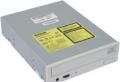
There are many implementations of Bluetooth modules. Each has its own characteristics, but in general they are all very similar. Consider a representative of the bluetooth module of the family HC-06which can be purchased at a great price on this site.
This module operates at frequencies from 2.40 GHz to 2.48 GHz and supports the bluetooth specification version 2.1 + EDR: lower power consumption, increased data security and easy connection of Bluetooth devices. Stable reception with the module is guaranteed within 10 meters.
The purpose of the pins of the bluetooth module is as follows:
The last two conclusions may not be involved; you can often find modules without these conclusions at all.
2 Connection diagrambluetooth module to Arduino
Let's connect the bluetooth module to the Arduino according to the diagram below. Note that the transmitter (Tx) of the Arduino is connected to the receiver (Rx) of the module, and vice versa.

On withdrawal Status a high level appears when the module is paired with another bluetooth device, and a low level when not paired. You can read its value by connecting it to the Arduino pin and assigning it an operating mode pinMode (pinStatus, INPUT) and thus know the state of the module. But the status indicator does not work correctly on all modules, so we will not use it in this example.
The result should be something like the photo.

3 Sketch for Arduinofor bluetooth operation
Let's write such a sketch and load it into Arduino memory:
Const int ledPin \u003d 13; // output of the built-in LED char incomingbyte; // variable for bluetooth data void setup () ( pinMode (ledPin, OUTPUT); Serial.begin (9600); ) void loop () ( if (Serial.available ()\u003e 0) (// if the port is available incomingbyte \u003d Serial.read (); // read data from the port switch (incomingbyte) (case "1": // if "1" comes digitalWrite (ledPin , HIGH); // break; case "0": // if "0" comes digitalWrite (ledPin, LOW); // break;)) }
We turn on the assembled circuit with the Arduino and the bluetooth module connected to it. A correctly connected module immediately enters the connection standby mode, which will be indicated by a rhythmically blinking status LED.
4 Pairingwith bluetooth device
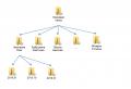
Now you need to add the bluetooth device to the list of trusted devices. Turn on Bluetooth on the computer, go to Bluetooth Device Settings.
If a bluetooth icon appears in the notification area when bluetooth is turned on on the computer, you can right-click on it and select the item:

We make sure that our bluetooth module is visible to the computer. Select it from the list and press the button To tie... In the dialog box, enter the default password 1234 ... If added successfully, the device will appear in the list with the mark Conjugated.

The default password for a specific module may differ from "1234". This information should be provided by the manufacturer (seller) of the module.
If you want to connect to your bluetooth module from a smartphone, then the procedure is the same: turn on bluetooth on your smartphone, detect the module connected to the Arduino, pair with it.
5 We connect to the bluetooth modulevia bluetooth from a computer
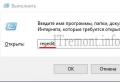
To connect to the bluetooth module, you can use various programs that can be connected to the COM port. For example, such as HyperTerminal, PuTTY, Tera Term, Termite and others. They are all free and freely distributed on the Internet.
Convenience of the program TeraTerm in that it automatically lists the COM ports that are assigned to the bluetooth module of your computer. Launch the program, select the Serial connection, select the corresponding bluetooth COM port from the list, click OK.

Program PuTTY at startup it also asks for the port number (COM4, \u200b\u200byou will have your own), connection speed (9600), connection type (Serial). Then press the button Connect.

In case of an error during connection, the program will display a corresponding notification. If the connection of your computer with the bluetooth module was successful, you will see a terminal field in front of you. Enter the number 1 from the keyboard in this field - and the LED on pin 13 of the Arduino will light up, enter 0 - it will go out.
6 Smartphone connectionvia Bluetooth Terminal
Similarly, you can connect to the bluetooth module from your smartphone. Download an application to work with bluetooth via a terminal, for example Bluetooth Terminal... Connect to the module and enter commands 0 or 1.
Thus, we learned how to connect via bluetooth to the Arduino and transfer data to it.
The HC-05 Bluetooth module is connected via the UART bus and is capable of executing AT commands. AT command is a line starting with the letters "AT" (from English attention - "attention"). The module executes the incoming command and sends back a response (the result of the command execution), which is also a string. In HC-05 Bluetooth modules, each command (as well as a response) must end with newline characters "\\ r \\ n".
Connection:
- You can control the HC-05 Bluetooth module either from a computer or through a microcontroller, for example, Arduino. The RX pin of the module is connected to the TX pin, and the TX pin of the module is connected to the RX pin of the device from which it will be controlled.
- To connect the module to a computer (without microcontrollers) you need a USB-UART adapter, or an RS232-UART adapter, or a programmer with TX RX pins, instead of a USB-UART adapter, you can use an Arduino board, as described in the article. To send commands to the module, you need to install the terminal program. One of these terminals is the free Termite program with Russian language support.
- To connect the module to Arduino you can use the hardware or software UART bus. When using the hardware bus, the module is connected to the TX and RX pins indicated on the board. When using the program bus, the module connects to the assignable TX and RX pins of the Arduino.
Setting:
The HC-05 Bluetooth module will only be able to receive commands if the following serial port parameters are configured correctly:
- roomport:It can be found out experimentally, unplug the adapter or Arduino, see what ports are available. Plug in the adapter or Arduino and see again which ports are available. The port that appears is the one.
- Data transfer rate:In normal mode, the HC-05 Bluetooth module keeps the last set baud rate, but by default it is 38400 bps (rarely 9600 bps). If both speeds don't work, see the note at the end of the article.
- Data transfer parameters:The module saves the last set data transmission parameters. Parameter values \u200b\u200bby default: number of bits in a packet - 8, stop bit size \u003d 1, no parity check.
- Transmitted text:You need to set the item "add CR & LF (NL) characters" these are line feed characters "\\ r \\ n" that you cannot put yourself at the end of AT commands.
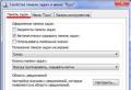
To configure these parameters in Termite, click on the Settings button. In the same window, you can set the Russian language.
When using Arduino, the port number is specified in the "Tools" tab. Data transfer parameters are used by default. Use the menu at the bottom right corner of the serial monitor to add NL & CR characters.
Verification:
After each power connection or module reboot, before sending commands, briefly press the module button. If the module does not have a button, then briefly send a high level to pin K. After that, the module will remain in normal mode, but will accept AT commands. Apart from the normal mode, the module can operate in the AT command mode. How to enter this mode and how it differs from the usual one is described below, in the note section.
To test communication with the Bluetooth module, send a test command AT(enter text ATand press Enter). If the connection is established correctly, the module will reply OK... After that, you can send the rest of the AT commands.
AT commands:
If the terminal program specifies to add CR & LF or NL & CR characters, then the characters "\\ r \\ n" do not need to be put in commands!
Commands can be usual: AT + COMMAND \\ r \\ n, queries: AT + COMMAND? \\ R \\ n, or settings: AT + COMMAND \u003d PARAMETER (S) \\ r \\ n.
| AT command: | Answer: | Purpose: | |
|---|---|---|---|
| AT | AT\\ r \\ n | OK \\ r \\ n | Test command: Used to check communication with the module. |
| RESET | AT + RESET\\ r \\ n | OK \\ r \\ n | The command to programmatically reload the module: The module behaves as after a short power outage. |
| VERSION | AT + VERSION?\\ r \\ n | + VERSION: VERSION\\ r \\ n OK \\ r \\ n |
Module firmware version request: The module returns the version as a string up to 32 bytes. Example response: + VERSION: hc01.comV2.1 \\ r \\ n OK \\ r \\ n |
| AT + ORGL | AT + ORGL\\ r \\ n | OK \\ r \\ n | Resetting custom settings: The module resets the following settings: CLASS \u003d 0, IAC \u003d 9e8b33, ROLE \u003d 0, CMODE \u003d 0, UART \u003d 38400,0,0, PSWD \u003d 1234, NAME \u003d hc01.com. |
| ADDR | AT + ADDR?\\ r \\ n | + ADDR: THE ADDRESS\\ r \\ n OK \\ r \\ n |
Module address request: The module returns three parts of its NAP address: UAP: LAP separated by a colon. Each part consists of hexadecimal digits. Example answer: + ADDR: 1234: 56: 789ABC \\ r \\ n OK \\ r \\ n |
| NAME | AT + NAME?\\ r \\ n | + NAME: NAME\\ r \\ n OK \\ r \\ n |
Request / set module name: The module name is represented by a string up to 32 bytes. Example answer: + NAME: iArduino \\ r \\ n OK \\ r \\ n Installation example: AT + NAME \u003d iArduino \\ r \\ n Some modules respond to the AT + NAME? \\ R \\ n command only when the module button is pressed or when input K is high. |
| AT + NAME \u003dNAME \\ r \\ n | OK \\ r \\ n | ||
| RNAME | AT + RNAME? ADDRESS \\ r \\ n | + RNAME: NAME\\ r \\ n OK \\ r \\ n |
Requesting the name of the found Bluetooth device: The address is entered after a space, and the parts of the address (NAP, UAP, LAP) are separated by commas. The module returns the name of the found Bluetooth device in range, the address of which was in the request. Example request: AT + NAME? 1234,56,789ABC \\ r \\ n Example answer: + RNAME: iArduino \\ r \\ n OK \\ r \\ n |
| ROLE | AT + ROLE?\\ r \\ n | + ROLE: ROLE\\ r \\ n OK \\ r \\ n |
Request / install module role: The role of the module is represented by a number: 0 - slave, 1 - master, 2 - slave in a cycle *. Example answer: + ROLE: 1 \\ r \\ n Installation example: AT + ROLE \u003d 0 \\ r \\ n |
| AT + ROLE \u003dROLE \\ r \\ n | OK \\ r \\ n | ||
| CLASS | AT + CLASS?\\ r \\ n | + CLASS: A TYPE\\ r \\ n OK \\ r \\ n |
Request / set device type: The device type is represented by a 32-bit number, which can be used to determine the purpose of the module: Bluetooth keyboard, Bluetooth mouse, headset ... Installation example: AT + CLASS \u003d 0 \\ r \\ n |
| AT + CLASS \u003dTYPE \\ r \\ n | OK \\ r \\ n | ||
| IAC | AT + IAC?\\ r \\ n | + IAC: THE CODE\\ r \\ n OK \\ r \\ n | Request / Set GIAC Sharing Code: The code is represented by a 32 bit number and is used to discover Bluetooth devices. In the role of the master, using this code, the module will gain access to other Bluetooth devices to search for them (polling), and in the role of the slave, this code will provide access to poll the module by other masters. Example answer: + IAC: 9e8b33 \\ r \\ n OK \\ r \\ n Installation example: AT + IAC \u003d 9e8b33 \\ r \\ n |
| AT + IAC \u003dCODE \\ r \\ n | OK \\ r \\ n or FAIL \\ r \\ n |
||
| INQM | AT + INQM?\\ r \\ n | + INQM: MODE,QTY,TIME\\ r \\ n OK \\ r \\ n |
Request / Set the module polling mode: The parameters used are settings for the command to search (poll) other Bluetooth devices. - Search mode is represented by a number: 0-standard, 1-search by signal strength. - The number is represented by a number defining the limit for the number of found Bluetooth devices, after which you want to stop searching. - Search time sets the timeout after which the search stops. The real search time in seconds is equal to the specified number multiplied by 1.28. Example answer: + INQM: 1,1,48 \\ r \\ n OK \\ r \\ n Installation example: AT + INQM: 1,1,48 \\ r \\ n |
| AT + INQM \u003dMODE, QTY, TIME \\ r \\ n | OK \\ r \\ n or FAIL \\ r \\ n |
||
| PSWD | AT + PSWD?\\ r \\ n | + PSWD: THE CODE\\ r \\ n OK \\ r \\ n |
Request / Set PIN: The access code is represented by a string up to 16 bytes. The module code as a slave device is the password for accessing the current module. The module code as a master device is a password for accessing external Bluetooth devices. Example answer: + PSWD: 1234 \\ r \\ n OK \\ r \\ n Installation example: AT + PSWD \u003d 1234arduino \\ r \\ n |
| AT + PSWD \u003dCODE \\ r \\ n | OK \\ r \\ n | ||
| UART | AT + UART?\\ r \\ n | + UART: SCOR,STOP,Check\\ r \\ n OK \\ r \\ n |
Request / Set UART Speed: The speed is represented by the number of bits / sec. Stop bit is represented by a digit: 0 - one, 1 - two Checking is represented by a number: 0 - no check, 1 - odd check, 2 - even parity. Example answer: + UART: 38400,0,0 \\ r \\ n OK \\ r \\ n Installation example: AT + UART \u003d 38400,0,0 \\ r \\ n |
| AT + UART \u003dSPEED, STOP, CHECK \\ r \\ n | OK \\ r \\ n | ||
| CMODE | AT + CMODE?\\ r \\ n | + CMOD: MODE\\ r \\ n OK \\ r \\ n |
Request / set connection mode: The mode is represented by a number: 0 - the module as a master connects only to the Bluetooth device, the address of which is specified by the AT + BIND command. 1 - the module as a master is connected to any slave Bluetooth device. 2 - the module as a slave works in a loop * Example answer: + CMOD: 0 \\ r \\ n OK \\ r \\ n Installation example: AT + CMOD \u003d 1 \\ r \\ n |
| AT + CMODE \u003dMODE \\ r \\ n | OK \\ r \\ n | ||
| BIND | AT + BIND?\\ r \\ n | + BIND: THE ADDRESS\\ r \\ n OK \\ r \\ n |
Request / set fixed address: If the module is in the role of the master (ROLE \u003d 1) and the mode of connecting to a fixed address (CMODE \u003d 0) is set, then it will connect only to the Bluetooth device whose address is specified by this command. Parts of the address are entered: during installation, separated by commas, and when answering, separated by colons. Example answer: + BIND: 1234: 56: 789ABC \\ r \\ n OK \\ r \\ n Installation example: AT + BIND \u003d 0,0,0 \\ r \\ n |
| AT + BIND \u003dADDRESS \\ r \\ n | OK \\ r \\ n | ||
| POLAR | AT + POLAR?\\ r \\ n | + POLAR: LOG,LOG\\ r \\ n OK \\ r \\ n |
Request / set an active logic level to turn on LEDs: Polarity is represented by the digit 0 or 1 corresponding to the active logic level. The first parameter indicates the logic level for turning on the LED connected to the PIO8 pin (displays the operating mode), and the second for the LED connected to the PIO9 pin (displays the connection status). Example answer: + POLAR: 1,1 \\ r \\ n OK \\ r \\ n Installation example: AT + POLAR \u003d 1,1 \\ r \\ n |
| AT + POLAR \u003dLOG, LOG \\ r \\ n | OK \\ r \\ n | ||
| PIO | AT + PIO \u003dNUMBER, LEVEL \\ r \\ n | OK \\ r \\ n | Setting the PIO logic level: Allows you to set the logic level on the PIO pin. The pin number is represented by a number from 2 to 11, except for 8 and 9. The level is represented by the number 0 or 1. Installation example: AT + PIO \u003d 11.0 \\ r \\ n |
| MPIO | AT + MPIO?\\ r \\ n | + MPIO: NUMBER\\ r \\ n OK \\ r \\ n |
Query / set PIO logic levels: Allows you to find out or set logic levels at once on all PIO pins. The levels are represented by a hexadecimal number, each bit of which corresponds to the level of the PIO pin. Example answer: + MPIO: 1F0 \\ r \\ n OK \\ r \\ n Installation example: AT + MPIO: CFC \\ r \\ n |
| AT + MPIO \u003dNUMBER \\ r \\ n | OK \\ r \\ n | ||
| IPSCAN | AT + IPSCAN?\\ r \\ n | + IPSCAN: AND,B,AT,D\\ r \\ n OK \\ r \\ n |
Request / Set IP Scan Parameters: A - scan interval B - scan duration B - page spacing Г - number of pages Example answer: + IPSCAN: 1024,512,1024,512 \\ r \\ n OK \\ r \\ n Installation example: AT + IPSCAN: 1024,512,1024,512 \\ r \\ n |
| AT + IPSCAN \u003dA, B, C, D \\ r \\ n | OK \\ r \\ n | ||
| SNIFF | AT + SNIFF?\\ r \\ n | + SNIFF: AND,B,AT,D\\ r \\ n OK \\ r \\ n |
Requesting / setting energy-saving mode parameters: A - maximum time B - minimum time B - repetition period G - timeout Example response: + SNIFF: 0,0,0,0 \\ r \\ n OK \\ r \\ n Installation example: AT + SNIFF \u003d 0,0,0,0 \\ r \\ n |
| AT + SNIFF \u003dA, B, C, D \\ r \\ n | OK \\ r \\ n | ||
| ENSNIFF | AT + ENSNIFF \u003dADDRESS \\ r \\ n | OK \\ r \\ n | Switching to energy saving mode: Example command: AT + ENSNIFF \u003d 1234,56,789ABC \\ r \\ n |
| EXSNIFF | AT + EXSNIFF \u003dADDRESS \\ r \\ n | OK \\ r \\ n | Exiting Power Saving Mode: Parts of the address are entered separated by commas (NAP, UAP, LAP) Example command: AT + EXSNIFF \u003d 1234,56,789ABC \\ r \\ n |
| SENM | AT + SENM?\\ r \\ n | + SENM: SECRET,CIPHER\\ r \\ n OK \\ r \\ n |
Requesting / setting security parameters: The secrecy mode is represented by the number: 0 - disabled 1 - unsecured connection 2 - protection at the service level 3 - connection level protection 4 - unknown mode The encryption mode is represented by a number: 0 - no encryption 1 - only PTP traffic is encrypted 2 - all traffic is encrypted Example answer: + SENM: 0,0 \\ r \\ n OK \\ r \\ n Installation example: AT + SENM: 0,0 \\ r \\ n |
| AT + SENM \u003dSECRET, CODE \\ r \\ n | OK \\ r \\ n | ||
| PMSAD | AT + PMSAD \u003dADDRESS \\ r \\ n | OK \\ r \\ n | Removing a device from the pair list: Removing a Bluetooth device from the list will result in the need to re-pair to connect to it. Parts of the address of the device to be deleted are entered separated by commas (NAP, UAP, LAP) Example command: AT + PMSAD \u003d 1234,56,789ABC \\ r \\ n |
| RMAAD | AT + RMAAD\\ r \\ n | OK \\ r \\ n | Removing all devices from the pair list: Clearing this list will lead to the need to re-pair with Bluetooth devices to connect to them. |
| FSAD | AT + FSAD \u003dADDRESS \\ r \\ n | OK \\ r \\ n or FAIL \\ r \\ n |
Search for a device in the pair list: If the Bluetooth device with the specified address is in the list, the module will return OK \\ r \\ n otherwise FAIL \\ r \\ n. Parts of the address are entered separated by commas (NAP, UAP, LAP) Example request: AT + FSAD \u003d 1234,56,789ABC \\ r \\ n |
| ADCN | AT + ADCN?\\ r \\ n | + ADCN: QUANTITY\\ r \\ n OK \\ r \\ n |
Request for the number of devices in the pair list: When a master-slave pair is formed, the pair data is automatically included in the pair list and for subsequent connections (even after power off), it is not necessary to re-pair. Example answer: + ADCN: 10 \\ r \\ n OK \\ r \\ n |
| MRAD | AT + MRAD?\\ r \\ n | + MRAD: THE ADDRESS\\ r \\ n OK \\ r \\ n |
Request for device address from the list of pairs: The module will return the Bluetooth address of the device from the list of pairs with which the last successful connection was made. Parts of the address are displayed with colon (NAP: UAP: LAP) Example answer: + MRAD: 1234: 56: 789ABC \\ r \\ n OK \\ r \\ n |
| STATE | AT + STATE?\\ r \\ n | + STATE: STATUS\\ r \\ n OK \\ r \\ n |
Module status request: The module will return its current state as a string: INITIALIZED - initialization READY - ready PAIRABLE - pairing PAIRED - pair formed INQUIRING - request CONNECTING - connection CONNECTED - connected DISCONNECTED - disconnected NUKNOW - unknown state Example answer: + STATE: CONNECTED \\ r \\ n OK \\ r \\ n |
| INIT | AT + INIT\\ r \\ n | OK \\ r \\ n or FAIL \\ r \\ n |
SPP profile initialization: The SPP profile emulates a serial port. |
| INQ | AT + INQ\\ r \\ n | + INQ: ADDRESS, TYPE, SIGNAL \\ r \\ n + INQ: ADDRESS, TYPE, SIGNAL \\ r \\ n ... + INQ: ADDRESS, TYPE, SIGNAL \\ r \\ n |
Searching (polling) Bluetooth devices: The module searches for Bluetooth devices in range and displays each found module on a new line. The search (polling) mode is set by the AT + INQM command, the polling code is set by the AT + IAC command, the type of devices to be searched is indicated by the AT + CLASS command. The search ends when the limit for the number of found Bluetooth devices is reached, or when the timeout is reached, or by the AT + INQC command. Example answer: + INQ: 1234: 56: 789ABС, 240404,7FFF |
| INQC | AT + INQC\\ r \\ n | OK \\ r \\ n | Finish searching (polling) Bluetooth devices: Early terminates the search for Bluetooth devices initiated by the AT + INQ command |
| PAIR | AT + PAIR \u003dADDRESS, TIMEOUT \\ r \\ n | OK \\ r \\ n or FAIL \\ r \\ n |
Pair with a Bluetooth device: Pairing or pairing of Bluetooth devices is initiated by the master device. The timeout is indicated by a decimal number in seconds. If a pair has been created, information about it will be automatically written to the list of pairs, the module will reply OK \\ r \\ n after which you can connect a Bluetooth device with the AT + LINK command. If the pair is not created (for example, the PIN code did not fit or the timeout expired), the module will reply FAIL \\ r \\ n. Example command: AT + PAIR \u003d 1234,56,789ABC, 10 \\ r \\ n |
| LINK | AT + LINK \u003dADDRESS \\ r \\ n | OK \\ r \\ n or FAIL \\ r \\ n |
Connect to Bluetooth device: After executing this command, you can communicate with the connected Bluetooth device. The team is available to the module as a leader. Example command: AT + LINK \u003d 1234,56,789ABC \\ r \\ n |
| DISC | AT + DISC\\ r \\ n | + DISC: RESULT\\ r \\ n OK \\ r \\ n |
Disconnect from Bluetooth device: The command tells the module to disconnect from the Bluetooth device with which the connection is established. After disconnecting from the Bluetooth device, information about it is saved in the list of pairs. If you need to reconnect to this device, then pairing will not be necessary (unless the Bluetooth device is deliberately removed from the pairing list). After executing the command, the module will respond with the result of its execution: SUCCESS - success LINK_LOSS - connection lost NO_SLC - no SLC TIMEOUT Timed out ERROR - error Example answer: + DISC: SUCCESS \\ r \\ n OK \\ r \\ n |
* Cycle driven is the slave role of the module in which it sends back everything it receives from the master.
** The module responds to some commands only when the module button is pressed or there is a high level on pin K.
Description of errors generated by the module:
If you send a command that the module does not know, cannot execute, or the command has incorrect arguments, the module will return the string “ERROR :( NUMBER) ", Where the specified hexadecimal number can be used to determine what the module is" swearing at ".
| Error no. | Error description |
|---|---|
| 0 | Invalid AT command (no such command) |
| 1 | Default result |
| 2 | Password save error |
| 3 | Device name too long (more than 32 bytes) |
| 4 | Device name not specified |
| 5 | Part of the NAP address is too long (more than 4 hex digits) |
| 6 | The UAP portion of the address is too long (more than 2 hex digits) |
| 7 | Part of LAP address too long (more than 6 hex digits) |
| 8 | PIO port mask not specified |
| 9 | PIO pin number not specified |
| A | The type (class) of the device is not specified |
| B | Device type (class) too long |
| C | General Inquire Access Code (IAC) not specified |
| D | Inquire Access Code (IAC) too long |
| E | Invalid General Inquire Access Code (IAC) |
| F | No password specified (or password is empty) |
| 10 | Password too long (more than 16 bytes) |
| 11 | Invalid module role |
| 12 | Invalid baud rate |
| 13 | Invalid stop bit size |
| 14 | Invalid parity bit setting |
| 15 | The device is not in the list of pairs (list of paired Bluetooth devices) |
| 16 | Serial Port Profile (SPP) not initialized |
| 17 | Reinitializing the SPP (Serial Port Profile) |
| 18 | Invalid polling mode for Bluetooth devices |
| 19 | Too long polling time |
| 1A | Bluetooth address not specified for device |
| 1B | Invalid security (secrecy) mode |
| 1C | Invalid encryption mode |
Note:
If you press the button or apply a high level to the K input immediately at the moment the module is turned on (power is applied), the module will go into AT commands mode. In this mode, the module will not connect with other modules, but this mode has a fixed speed \u003d 38400 bps. If during setup, in the normal mode of the module operation, you could not determine the speed of the module, you can enter this mode and set a new speed. The newly set speed will take effect only in normal mode, for this you will need to restart the module without holding the button and without giving a high level to the K input at the moment of switching on. Remember that in normal mode, not earlier than half a second after power-on (or reboot), you need to briefly press the button or apply a short-term high level to the K input of the module, otherwise it will not accept AT commands.
If you want to be able to "push" the button programmatically, but your module does not have the K pin, use the command AT + PIO \u003d 11, LEVEL\\ r \\ n , where the level is represented by the number 1 or 0 corresponding to the set logic level. ( AT + PIO \u003d 11.0\\ r \\ n - the button is released , AT + PIO \u003d 11.1\\ r \\ n - button pressed).
Some modules have an En pin that controls power and is pulled up to Vcc. If a low logic level is applied to the En pin, the power supply of the chips is turned off. This pin can be used to programmatically enter AT command mode. If immediately after removing the low level from the En pin, issue the command AT + PIO \u003d 11.1 \\ r \\ n, this will be equivalent to turning on the module with the button pressed.
Create a slave pending master connection:
- AT + DISC
- AT + ORGL
- AT + RMAAD\\ r \\ n - Clear the list of pairs (authorized devices) so that the one who was disconnected does not connect to the module.
- AT + NAME \u003diArduino \\ r \\ n - Set the module name (max 32 characters).
- AT + PSWD \u003d1234 \\ r \\ n - Set PIN-code for connection to the module (no more than 16 characters).
- AT + ROLE \u003d 0\\ r \\ n - Set the module to the slave role (if it was not installed when resetting user settings).
- AT + RESET\\ r \\ n - Reload the module.
Not earlier than half a second after rebooting (with the command AT + RESET\\ r \\ n), you need to shortly press the button or send a short-term high level to the K input of the module, otherwise it will not accept new AT commands.
If the module with the leading role is connected to the slave modules by their address, and not through their name, then the address of this (slave) module can be found by executing the command AT + ADDR? \\ R \\ n.
Creating a master with a slave connection:
- AT + DISC\\ r \\ n - Break the connection (in case the module is connected).
- AT + ORGL\\ r \\ n - Reset user settings to default values.
- AT + RMAAD\\ r \\ n - Clear the list of pairs (authorized devices) so that the module does not try to connect to the one it was disconnected from.
- AT + BIND \u003dADDRESS \\ r \\ n - Set a fixed address for connection (specify the address of the slave Bluetooth device)
- AT + CMODE \u003d 0\\ r \\ n - We tell the module to connect only to a fixed address
- AT + ROLE \u003d 1\\ r \\ n - Set the module to the role of the master
- AT + PSWD \u003d1234 \\ r \\ n - Remember the PIN-code of the slave Bluetooth device
- AT + PAIR \u003dADDRESS, 10 \\ r \\ n - Form a pair with a slave Bluetooth device, specifying its address and a timeout of 10 seconds .
Bluetooth whistle for computer: http://ali.pub/2jfj3y
First, let's figure out what bluetooth is.
Bluetooth (from the English words blue - blue and tooth - tooth; pronounced / bluːtuːθ /), bluetooth - production specification for wireless personal area networks ( Wireless personal area network, WPAN). Bluetooth enables the exchange of information between devices such as personal computers (desktops, handhelds, laptops), mobile phones, printers, digital cameras, mice, keyboards, joysticks, headphones, headsets on a reliable, free, universally available radio frequency for short-range communications. Bluetooth allows these devices to communicate when they are within a radius of up to 10 meters from each other (range is highly dependent on obstacles and interference), even in different rooms.
Now, knowing that bluetooth is used to build networks and exchange data between devices, we will use it to connect a CNC machine tool and a computer or a phone or tablet and a laptop.
Since I use the grbl firmware on the arduino platform to control the CNC, we will connect a bluetooth module suitable for arduino to the machine, namely the bluetooth module HC-06.
Before connecting the Bluetooth module to the arduino, you need to make sure that the Bluetooth module and the arduino work at the same COM port speed.
If you are using firmware grbl 0.8, then nothing needs to be changed, but if grbl 0.9 and higher, then the COM port speed of the arduino will become 115200, and the default speed on the module is 9600.
So we need to change the port speed on the bluetooth module itself.
For configuring Bluetooth modules, there are special AT commands, with which we can set the required module parameters.
With AT commands, we can change the speed of the COM port or change the name of the Bluetooth device or find out or change the pin code for pairing.
In order to connect a bluetooth module to a computer to enter AT commands, we need a FTDI programmer, link to it at the beginning of the article. I think the connection diagram is unnecessary here. You need to connect gnd to gnd, 5v to 5v, rx to tx and tx to rx.
After connecting, we need the HMComAssistant program to enter AT commands and program our module. Download: https://yadi.sk/d/eVzPmnh63Wab5R
Well, here I will give some AT commands to change the settings of the bluetooth module:
| AT command | Module response | Comment |
|---|---|---|
| AT | OK | It is used to check the connection, as a rule, before performing any operations, this command is first used to check the connection. |
| AT + BAUD1 | OK or OK1200 | Sets the baud rate to 1200 baud |
| AT + BAUD2 | OK or OK2400 | Sets the baud rate to 2400 baud |
| AT + BAUD3 | OK or OK4800 | Sets the baud rate to 4800 baud |
| AT + BAUD4 | OK or OK9600 | Sets the baud rate to 9600 baud |
| AT + BAUD5 | OK or OK19200 | Sets the baud rate to 19200 baud |
| AT + BAUD6 | OK or OK38400 | Sets the baud rate to 38400 baud |
| AT + BAUD7 | OK or OK57600 | Sets the baud rate to 57600 baud |
| AT + BAUD8 | OK or OK115200 | Sets the baud rate to 115200 baud |
| AT + BAUD9 | OK or OK230400 | Sets the baud rate to 230400 baud |
| AT + BAUDA | OK or OK460800 | Sets the baud rate to 460800 baud |
| AT + BAUDB | OK or OK921600 | Sets the baud rate to 921600 baud |
| AT + BAUDC | OK or OK1382400 | Sets the baud rate to 1382400 baud |
| AT + NAME | + NAME \u003d test | Returns the current name of the module |
| AT + NAMEiarduino_BLU | + NAME \u003d test OK | Sets the new module name “test“ |
| AT + PIN | + PIN \u003d 000000 | Returns the current password, in this case the password is “000000” |
| AT + PIN123456 | + PIN \u003d 123456 OK | Set a new password, in this case the password is “123456” |
| AT + VERSION | + VERSION \u003d Firmware V3.0.6, Bluetooth V4.0 LE | Returns the firmware version, in this case the password is “Firmware V3.0.6, Bluetooth V4.0 LE” |
| AT + RESET | + RESET OK | |
| AT + HELP | ——– | Returns a list of all available AT commands |
After changing the speed of the com port and setting the pin code for pairing. (by default the pin code for pairing is “1234”, let's connect the module to the arduino.
And since I am using CNC shield v 3.0. Then I will give the connection diagram to it.
I will not create my own scheme, but I will take from one article. May her creator forgive me.

The scheme is certainly not very flat, but in my opinion it is quite clear.
So what are resistors used in the circuit? Arduino has 5 volt logic, which means that the arduino sends a voltage of 5V to all outputs. But the module says LEVEL 3.3v, which means that Bluetooth requires 3.3V, but not 5v. Therefore, resistors are connected to lower the voltage and prevent the failure of the bluetooth module.
But I decided to use it directly without resistors, let's see how long the module will last, we will arrange a certain crash test.
To control a CNC machine from a phone or tablet, I used the “Grbl controller” program, which is free and quite multifunctional. In the video below, I briefly showed how the machine is controlled from this program.
But if you connect from a computer, then there is a nuance, when pairing the connection with the module, two new COM ports will appear in the devices. I have it COM6 and COM7. So one of them is for sending data, and the other for receiving. Therefore, there is no need to be scared and just try to connect to one, if nothing happens then connect to another.
But if something is not clear, but I clearly showed it in the video: