Ip version 4 tcp ipv4 windows 10. IPv6: configuration in Windows systems
Today there was an interesting copy running OS win 8. I had to tinker with it. Initially, when loading, there was a black screen after the logo. By manipulating the registry branches in the backup, it was possible to return it as it was. Moreover, regular recovery and rollback to the point fell out with errors. As a result, I downloaded the beast, but found that the Internet did not work until the heap. Moreover, it refuses to ping exactly network DNS names, including even localhost. In order not to immediately use heavy artillery, I decided to try more gentle options.
reset windows routing table
First, I decided to make sure that viruses did not shove through the routing table. In order to return everything as originally intended by small soft, you must execute the following command by running cmd .
And then reboot the patient. But in this case, this was not the problem, and we went further.
Reset WinSock
I decided to heap, if he doesn’t plow anything, do a dump Winsock... For this action it is also necessary in the command line cmd run the command:
Then we reboot. We check the ping to ya.ru. In my case, the answer is still no. So I had to move on.
Reinstalling TCP / IP
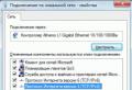
And then, I decided not to look for ways to get around the trouble, but to shoot at it with a cannon, so to speak. We will reinstall the TCP / IP protocol, completely. Initially, if you pass Control Panel -> Network and Internet -> -> Properties, and highlight Internet Protocol Version 4 (TCP / IP), we will see that this protocol cannot be deleted ..

We will do so that it is possible. To do this, we carry out everything point by point.
1) You need to delete 2 keys in the registry. We start the registry through the command regedit in Execute (win + R) or through Start and in the field Find programs and fileswe write regedit... Next, we search for and delete the following branches:
HKEY_LOCAL_MACHINE \\ System \\ CurrentControlSet \\ Services \\ Winsock
HKEY_LOCAL_MACHINE \\ System \\ CurrentControlSet \\ Services \\ WinSock2 \\
2) Next, you need to find the file Nettcpip.inf, which is located on the system drive in the folder Windows \\ inf... We open it with any editor, including Notepad and look for a section almost at the top of the file and a line in it Characteristics \u003d 0xa0... Change the parameter value Characteristics \u003d 0xa0 on 0x80... There may be problems saving this file in the inf directory. I advise you to save as after the changes and save it to your desktop. Next, try to copy it with replacement in Windows \\ inf... If this does not work out, then most likely you have a system record as the owner of the file TrustedInstaller... You must take ownership of this file. To do this, pkm on the file, Properties-> security tab -> Additionally -> owner tab -> Edit, and select the user we want to set as owner. Better yourself 🙂 Well, then we expose the user group Full access. Now we can do everything with this file, whatever we want.
3) Let's go back to the network connection. Control Panel -> Network and Internet -> Network and Sharing Center -> Change adapter settings,click pcm on network connection Properties... We press Install -> Protocol -> Install from disk -\u003e Using the button Overview point the way to System Drive: \\ Windows \\ infand click OK. Select at the bottom of the list Internet Protocol Version 4 (TCP / IPv4)and click OK.

Now, returning to the Local Area Connection Properties, and having entered the Internet Protocol version 4, we should see that the button Delete became active.
4) Actually delete the protocol, reboot and go through the whole point №3 again. Reboot again and check the internet.
In my case, everything worked for another point №3 without deleting the protocol.
IP addresses (Internet Protocol version 4, Internet Protocol version 4) - represent the main type of addresses used at the network layer of the OSI model to transfer packets between networks. IP addresses are four bytes, for example 192.168.100.111.
The assignment of IP addresses to hosts is carried out:
- manually, configured by the system administrator when setting up a computer network;
- automatically, using special protocols (in particular, using DHCP - Dynamic Host Configuration Protocol).
IPv4 protocol developed in September 1981.
IPv4 protocol works at the gateway (network) layer of the TCP / IP protocol stack. The main task of the protocol is to transfer data blocks (datagrams) from the sending host to the destination host, where the senders and receivers are computers that are uniquely identified by fixed-length addresses (IP addresses). Also, the Internet Protocol IP performs, if necessary, fragmentation and collection of sent datagrams for data transmission over other networks with smaller packet size.
The disadvantage of the IP protocol is the unreliability of the protocol, that is, before the start of transmission, a connection is not established, this indicates that the delivery of packets is not confirmed, the correctness of the received data is not checked (using the checksum) and the handshake operation is not performed (exchange of service messages with the node - destination and its readiness to receive packages).
The IP protocol sends and processes each datagram as an independent chunk of data, that is, it has no other connection with other datagrams on the global Internet.
After a datagram is sent to the network by the IP protocol, further actions with this datagram are not in any way controlled by the sender. It turns out that if the datagram, for some reason, cannot be transmitted further along the network, it is destroyed. Although the host that destroyed the datagram has the ability to report the cause of the failure to the sender, by the return address (in particular, using the ICMP protocol). The guarantee of data delivery is assigned to the higher-level protocols (transport layer), which are endowed with special mechanisms for this (TCP protocol).
As you know, routers operate at the network layer of the OSI model. Therefore, one of the most basic tasks of the IP protocol is the implementation of routing of datagrams, in other words, determining the optimal route of datagrams (using routing algorithms) from the source node of the network to any other node on the network based on the IP address.
At some node on the network receiving a datagram from the network looks like this:

IP header format
The structure of version 4 IP packets is shown in the figure

- Version - for IPv4, the field value must be 4.
- IHL - (Internet Header Length) The length of the IP packet header in 32-bit words (dword). It is this field that indicates the beginning of the data block in the packet. The minimum valid value for this field is 5.
- Type of Service (acronym TOS) - a byte containing a set of criteria that determine the type of service for IP packets, shown in the figure.

Service byte description bit by bit:
- 0-2 is the precedence of this IP segment
- 3 - the requirement for the delay time (delay) of the transmission of the IP segment (0 - normal, 1 - low delay)
- 4 - the requirement for the throughput of the route along which the IP segment should be sent (0 - low, 1 - high throughput)
- 5 - requirement for reliability of IP segment transmission (0 - normal, 1 - high reliability)
- 6-7 - ECN - Explicit Delay Message (IP Flow Control).
- Packet length - the length of the packet in octets, including header and data. The minimum valid value for this field is 20, the maximum is 65535.
- Identifier is a value assigned by the sender of a packet and intended to determine the correct sequence of fragments when assembling a packet. For a fragmented packet, all fragments have the same identifier.
- 3 bits of flags. The first bit must always be zero, the second DF (don’t fragment) bit determines whether the packet is fragmented, and the third MF (more fragments) bit indicates whether this packet is the last in the packet chain.
- Fragment offset is a value that determines the position of the fragment in the data stream. The offset is given by the number of eight byte blocks, so this value needs to be multiplied by 8 to convert to bytes.
- Time to Live (TTL) is the number of routers this packet must pass. When passing through the router, this number will decrease by one. If the value of this field is equal to zero, then the packet must be discarded and a Time Exceeded message (ICMP code 11 type 0) can be sent to the sender of the packet.
- Protocol - The next layer Internet protocol identifier indicates which protocol data the packet contains, for example, TCP or ICMP.
- Header Checksum - Calculated per RFC 1071
Intercepted IPv4 packet using Wireshark sniffer:

Fragmentation of IP packets
On the path of the packet from the sender to the receiver, there can be local and global networks of different types with different allowable sizes of data fields of the data link-layer frames (Maximum Transfer Unit - MTU). For example, Ethernet networks can transmit frames carrying up to 1500 bytes of data, X.25 networks are characterized by a frame data field of 128 bytes, FDDI networks can transmit frames of 4500 bytes, other networks have their own limitations. The IP protocol is able to transmit datagrams, the length of which is longer than the MTU of the intermediate network, due to fragmentation - splitting the "large packet" into a number of parts (fragments), the size of each of which satisfies the intermediate network. After all the fragments have been transmitted through the intermediate network, they will be assembled at the receiving node by the IP protocol module back into a “big packet”. Note that only the receiver does the assembly of a packet from fragments, and not any of the intermediate routers. Routers can only fragment packets, not collect them. This is because different fragments of the same packet will not necessarily go through the same routers.
In order not to confuse fragments of different packets, the Identification field is used, the value of which must be the same for all fragments of one packet and not be repeated for different packets until both packets have expired. When dividing the packet data, the size of all fragments, except for the last one, must be a multiple of 8 bytes. This allows less heading space to be allocated under the Fragment Offset field.
The second bit of the Flags field (More fragments), if equal to one, indicates that this fragment is not the last in the packet. If the packet is sent without fragmentation, the More fragments flag is set to 0 and the Fragment Offset field is filled with zero bits.
If the first bit of the Flags (Don’t fragment) field is one, then packet fragmentation is prohibited. If this packet is to be transmitted over a network with insufficient MTU, then the router will have to discard it (and inform the sender about it via the ICMP protocol). This flag is used when the sender knows that the receiver does not have sufficient resources to recover packets from fragments.
All IP addresses can be divided into two logical parts - network numbers and host numbers (host number). To determine which part of the IP address belongs to the network number, and which part to the host number, it is determined by the values \u200b\u200bof the first bits of the address. Also, the first bits of an IP address are used to determine which class a particular IP address belongs to.
The figure shows the structure of an IP address of different classes.

If the address starts with 0, then the network is classified as class A and the network number occupies one byte, the remaining 3 bytes are interpreted as a node number in the network. Class A networks have numbers in the range from 1 to 126. (Number 0 is not used, and number 127 is reserved for special purposes, which will be discussed below.) Class A networks are few, but the number of nodes in them can reach 2 24, that is 16,777,216 knots.
If the first two bits of the address are 10, then the network belongs to class B. In class B networks, 16 bits are allocated for the network number and for the node number, that is, 2 bytes. Thus, the class B network is a medium-sized network with a maximum number of nodes of 2-16, which is 65,536 nodes.
If the address starts with the sequence 110, then this is a class C network. In this case, 24 bits are allocated for the network number, and 8 bits for the node number. Networks of this class are the most common, the number of nodes in them is limited to 2 8, that is, 256 nodes.
If the address starts with the sequence 1110, then it is a class D address and denotes a special, multicast address. If a class D address is specified in a packet as a destination address, then such a packet must be received by all nodes to which this address is assigned.
If the address begins with the sequence 11110, then this means that this address belongs to class E. Addresses of this class are reserved for future use.
The table shows the ranges of network numbers and the maximum number of nodes corresponding to each class of networks.

Large networks receive class A addresses, medium-sized networks receive class B addresses, and small networks receive class C.
Using masks in IP addressing
In order to obtain one or another range of IP addresses, enterprises were asked to fill out a registration form, which listed the current number of computers and the planned increase in the number of computers, and as a result, the enterprise was given a class of IP addresses: A, B, C, depending on the specified data in the registration form.
This mechanism for issuing ranges of IP addresses worked normally, this was due to the fact that at first the organizations had a small number of computers and, accordingly, small computer networks. But in connection with the further rapid growth of the Internet and network technologies, the described approach to the distribution of IP addresses began to fail, mainly associated with class "B" networks. Indeed, organizations in which the number of computers did not exceed a few hundred (say, 500) had to register an entire class B network for themselves (since class C only for 254 computers, and class B for 65534). Because of what the available class "B" networks became, simply, not enough, but at the same time large ranges of IP-addresses were wasted.
The traditional scheme for dividing an IP address into network number (NetID) and host number (HostID) is based on the concept of a class, which is determined by the values \u200b\u200bof the first few bits of the address. Precisely because the first byte of address 185.23.44.206 falls in the range 128-191, we can say that this address belongs to class B, which means that the network number is the first two bytes, supplemented by two zero bytes - 185.23.0.0, and the number node - 0.0.44.206.
But what if we use some other feature, with the help of which it would be possible to more flexibly set the boundary between the network number and the node number? Masks are now widely used as such a feature.
Mask is a number that is paired with an IP address; the binary record of the mask contains ones in those digits that should be interpreted as a network number in the IP address. Since the network number is an integral part of the address, the units in the mask must also represent a continuous sequence.
For standard network classes, masks have the following meanings:
- class A - 11111111. 00000000. 00000000. 00000000 (255.0.0.0);
- class B - 11111111.111111110000000000000000 (255.255.0.0);
- class C - 11111111.11111111.11111111. 00000000 (255.255.255.0).
By supplying each IP address with a mask, you can eliminate the concept of address classes and make the addressing system more flexible. For example, if the address 185.23.44.206 discussed above is associated with the mask 255.255.255.0, then the network number will be 185.23.44.0, and not 185.23.0.0, as defined by the class system.
Calculating the network number and node number using a mask:

In masks, the number of ones in the sequence defining the boundary of the network number does not have to be a multiple of 8 to repeat the division of the address into bytes. For example, let the mask 255.255.128.0 be specified for the IP address 129.64.134.5, that is, in binary:
- IP address 129.64.134.5 - 10000001. 01000000.10000110. 00000101
- Mask 255.255.128.0 - 11111111.11111111.10000000. 00000000
If you ignore the mask, then in accordance with the class system, the address 129.64.134.5 belongs to class B, which means that the network number is the first 2 bytes - 129.64.0.0, and the node number - 0.0.134.5.
If we use a mask to determine the boundary of the network number, then 17 consecutive units in the mask, "superimposed" (logical multiplication) on the IP address, determine the number as the network number in binary expression:

or in decimal notation - the network number is 129.64.128.0, and the node number is 0.0.6.5.
There is also a short version of the mask notation called prefix or a short mask. In particular, the network 80.255.147.32 with the mask 255.255.255.252 can be written as 80.255.147.32/30, where "/ 30" indicates the number of binary ones in the mask, that is, thirty binary ones (counting from left to right).
For clarity, the table displays the correspondence between the prefix and the mask:

The mask mechanism is widespread in IP routing, and masks can be used for a wide variety of purposes. With their help, the administrator can structure his network without requiring additional network numbers from the service provider. Based on the same mechanism, service providers can combine address spaces of several networks by introducing so-called “ prefixes»In order to reduce the size of the routing tables and thereby increase the performance of routers. In addition, writing the mask as a prefix is \u200b\u200bmuch shorter.
Special IP addresses
In the IP protocol, there are several conventions about the special interpretation of IP addresses:
- 0.0.0.0 - represents the default gateway address, i.e. the address of the computer to which information packets should be sent if they did not find the destination in the local network (routing table);
- 255.255.255.255 - broadcast address. Messages sent to this address are received by all nodes of the local network containing the message source computer (it is not transmitted to other local networks);
- “Network number.” “All zeros” - network address (for example 192.168.10.0);
- “All zeros.” “Node number” is a node in this network (for example, 0.0.0.23). Can be used to send messages to a specific node within a local network;
- If the destination node number field contains only ones, then a packet with such an address is sent to all network nodes with a given network number. For example, a packet with the address 192.190.21.255 is delivered to all hosts on the 192.190.21.0 network. This broadcast is called a broadcast. When addressing, it is necessary to take into account those restrictions that are introduced by the special assignment of some IP addresses. So, neither the network number nor the node number can consist of only one binary ones or only one binary zeros. It follows that the maximum number of nodes given in the table for networks of each class should be reduced by 2 in practice. For example, in class C networks, 8 bits are allocated for the node number, which allow you to set 256 numbers: from 0 to 255. However, on In practice, the maximum number of nodes in a class C network cannot exceed 254, since addresses 0 and 255 have a special purpose. From the same considerations, it follows that the end node cannot have an address of type 98.255.255.255, since the node number in this class A address consists of only binary ones.
- The IP address has a special meaning, the first octet of which is 127.х.х.х. It is used to test programs and process interactions within a single machine. When the program sends data to the IP address 127.0.0.1, it forms a kind of "loop". The data is not transmitted over the network, but is returned to the higher-level modules as it has just been received. Therefore, in an IP network, it is prohibited to assign IP addresses to machines starting with 127. This address is called loopback. You can assign address 127.0.0.0 to the internal network of the node routing module, and address 127.0.0.1 to the address of this module on the internal network. In fact, any network address 127.0.0.0 serves to designate its own routing module, not just 127.0.0.1, for example 127.0.0.3.
In the IP protocol there is no concept of broadcasting in the sense in which it is used in the data link layer protocols of local networks, when data must be delivered to absolutely all nodes. Both the restricted broadcast IP address and the broadcast IP address have limits on the Internet — they are limited either to the network to which the packet's source node belongs, or to the network specified in the destination address. Therefore, dividing the network with routers into parts localizes the broadcast storm outside one of the parts of the overall network, simply because there is no way to address the packet simultaneously to all nodes of all networks of the composite network.
IP addresses used in local networks
All addresses used on the Internet must be registered in order to guarantee their uniqueness on a global scale. Such addresses are called real or public IP addresses.
For local networks that are not connected to the Internet, registration of IP addresses is naturally not required, since, in principle, any possible addresses can be used here. However, in order to avoid the possibility of conflicts during the subsequent connection of such a network to the Internet, it is recommended to use only the following ranges of so-called private IP addresses in local networks (these addresses do not exist on the Internet and cannot be used there), presented in the table.
Every owner of a personal computer or laptop has encountered problems with access to the Internet. It so happened that all the settings were made, there was access to the network, Wi-Fi was configured, but there was no access to the Internet. In network connections, the status bar says the following: IPv4 without internet access. How to fix the error and access the network, read this article.
Error diagnostics
The first thing to do in this situation is to diagnose the networks:
- Press Win + R and run the command ncpa.cpl
- Right click on the problematic network connection and select "Status".
- Open Diagnostics.
- Depending on the identified problem, to solve it, use the material on the links provided:
- One or more network protocols are missing on this computer.

- .

- The computer settings are configured correctly, but the device or resource (DNS server) is not responding.

- .

- DHCP server is not enabled on the network adapter.

- One or more network protocols are missing on this computer.
It often happens that an incorrectly configured DHCP server is the cause of a problem with Internet access. This can be both from your side and from the side of the Internet provider. If you have exactly this problem, read on.
TCP / IPv4 Settings
First, let's make sure that there is no normal network failure that can be resolved by reconnecting the connection. Right click on the problematic network and select "Disable". Then, with a double click of the mouse, turn it back on.  If you have a router, restart it too. If there are multiple computers on the network, do not assign the problematic IP address to another device. If you do this, the network will not work.
Router settings
If you are using a router, enable the DHCP server in the DHCP settings:

If the suggested options did not help to fix the problem, contact the technical support of your provider. For their part, they will analyze possible errors and indicate what is the reason for the lack of the Internet.
Every owner of a personal computer or laptop has encountered problems with access to the Internet. It so happened that all the settings were made, there was access to the network, Wi-Fi was configured, but there was no access to the Internet. In network connections, the status bar says the following: IPv4 without internet access. How to fix the error and access the network, read this article.
Error diagnostics
The first thing to do in this situation is to diagnose the networks:
- Press Win + R and run the command ncpa.cpl
- Right click on the problematic network connection and select "Status".
- Open Diagnostics.
- Depending on the identified problem, to solve it, use the material on the links provided:
- .
- .
- .
- .
- DHCP server is not enabled on the network adapter.
- .
It often happens that an incorrectly configured DHCP server is the cause of a problem with Internet access. This can be both from your side and from the side of the Internet provider. If you have exactly this problem, read on.
TCP / IPv4 Settings
First, let's make sure that there is no normal network failure that can be resolved by reconnecting the connection. Right click on the problematic network and select "Disable". Then, with a double click of the mouse, turn it back on. If you have a router, restart it too. If there are multiple computers on the network, do not assign the problematic IP address to another device. If you do this, the network will not work.
Router settings
If you are using a router, enable the DHCP server in the DHCP settings:
If the suggested options did not help to fix the problem, contact the technical support of your provider. For their part, they will analyze possible errors and indicate what is the reason for the lack of the Internet.
Related entries:
 192.168 1.2 login to the tp link router. The computer does not receive an IP address from the router. Alternative ways to enter the Wi-Fi router or modem settings
 IPv6: Configuring on Windows Systems
 Additional Internet packages
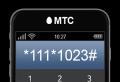
 How to connect a profitable long distance to MTS
 Description of tariff Smart mini MTS


