Manufacturing of a device for measuring the capacitance of capacitors. DIY ESR meter - capacitor capacitance meter. Scheme and description. For the diagram "Capacitance meter on a logical element"
Sometimes a capacitor is not labeled. How to find out then its real capacity if there is no special equipment at hand, and the device is unmarked? Then various improvised means and formulas come to the rescue. Before starting work, it must be remembered that the capacitor must be discharged before testing (its contacts must be discharged). To do this, you can use a standard screwdriver with an insulated handle. Holding the handle with a screwdriver, touch the contacts, thus closing them. Next, we will tell you in detail how to determine the capacitance of a capacitor with a multimeter, providing instructions with a video example.
Using the "Cx" mode
After the contacts have been short-circuited, resistance determination can be carried out. If the element is fixed, then immediately after connecting it will begin to charge with constant current. In this case, the resistance will be displayed as minimal and will continue to grow.
If the capacitor is faulty, then the multimeter will immediately indicate infinity or will indicate zero resistance and at the same time beep. This check is carried out if the design is polar.
In order to find out the capacity, you must have a multimeter with the function of measuring the "Cx" parameter.
It is easy to determine the capacitance using such a multimeter: set it to the "Cx" mode and indicate the minimum measurement limit that this capacitor should have. These multimeters have special jacks with certain measurement limits. A capacitor is inserted into these slots according to its measurement limit and its parameters are determined.
If there are no such nests in the tester, then you can determine the capacity using measuring probes, as shown in the photo below:

Important! In a separate article, we talked about. We also recommend that you familiarize yourself with this material!
Applying formulas
What if you don't have such a multimeter with measurement jacks at hand, but there is only an ordinary household appliance? In this case, you need to remember the laws of physics that will help determine the capacity.
To begin with, remember that in the case when a capacitor is charged from a constant voltage source through a resistor, then there is a regularity according to which the voltage on the device will approach the source voltage and will eventually equal it.

But in order not to expect this, the process can be simplified. For example, within a certain time, which is equal to 3 * RC, during charging, the cell reaches 95% of the voltage applied to the RC circuit. Thus, the time constant can be determined from the current and voltage. And more correctly, if you know the voltage in the power supply, the value of the resistor itself, the time constant is determined, and then the capacity of the device.

For example, there is an electrolytic capacitor, the capacity of which can be recognized by the marking, where 6800 uF 50V is prescribed. But what if the device has been lying idle for a long time, and it is difficult to determine its working condition from the inscription? In this case, it is better to check its capacity to know for sure.
To do this, do the following:

How to determine the capacitance of a ceramic capacitor? In this case, you can make a determination using a network transformer. For this, the RC-chain is connected to the secondary winding of the transformer, and it is connected to the network. Further, using a multimeter, the voltage across the capacitor and across the resistor is measured. After that, it is necessary to make calculations: the current that passes through the resistor is calculated, then its voltage is divided by the resistance. It turns out the capacitive resistance Xc.

If there is a current frequency and Xc, you can determine the capacitance by the formula:

Other techniques
Also, the capacity can be determined using a ballistic galvanometer. For this, the formula is used:

- Cq is the ballistic constant of the galvanometer;
- U2 - voltmeter readings;
- a2 - angle of deflection of the galvanometer.

The determination of the value by the ammeter of the voltmeter is carried out as follows: the voltage and current in the circuit are measured, after which the value of the capacitance is determined by the formula:

The voltage with this method of determination must be sinusoidal.

Measurement is also possible with a bridge circuit. In this case, the AC bridge circuit is indicated below:

Here one shoulder of the bridge is formed by the element to be measured (Cx). The next leg consists of a lossless capacitor and a resistance box. The remaining two arms are composed of resistance stores. We connect the power supply to one diagonal, and the zero indicator to the other. And we calculate the value using the formula:

Electrical circuits, consisting of conductors and semiconductors, include elements that allow you to accumulate charges and release them at the right time. Because of this feature, such elements were originally called capacity. The name comes from the time when electricity was considered a liquid, and its storage device was a vessel. This not entirely successful definition is still used today, although the element itself is called a capacitor.
Condenser design and characteristics
The capacitor design consists of two conductive plates separated by a dielectric. If you apply a voltage to the plates from a DC source, then the current will flow through the capacitor for a short time, and it will be charged. A voltage equal to the voltage of the source will accumulate on its plates (plates). The duration of the current flow and the capacity of its charge depend on the area of \u200b\u200bthe plates and the distance between them. Capacity is designated with the letter C and is measured in farads. The SI unit is 1F (F). The designation was adopted in honor of the physicist from England M. Faraday.
Attention! Capacity 1F is a very large value. If we consider the Earth as a solitary conductor in the shape of a ball, then the capacitance would be about 700 μF. Therefore, electrical elements are measured in small quantities: picofarads (pF), nanofarads (nF), microfarads (μF).

In DC and AC circuits, the capacitive element behaves differently. If the capacitor does not pass direct current through itself, then the alternating current passing through it has a certain resistance. This is another important characteristic of a capacitor - the RC capacitance.
Resistance from the category of reactance is calculated by the formula:
Rс \u003d 1 / 6.28 * f * C,
- Rc - capacitive resistance, Ohm;
- 6.28-2 π;
- f - current frequency, Hz;
- C is the capacity of this capacitor, F.
Important! As can be seen from the formula, for currents of different frequencies, the resistance of the same element changes. The higher the current frequency, the lower the capacitance of the capacitor.
Distinguish between capacitors of constant and variable capacitance. The latter have a design that changes the distance between the plates.
By the type of execution, capacitors of constant capacitance are:
- polar electrolytic;
- single-layer and multi-layer ceramic;
- high voltage ceramic;
- polyester;
- tantalum;
- polypropylene capacitors.
The design depends on the ordinal discharge of the capacitance of the element, the material used for the plates and the dielectric.
Capacitor designations
The amount of data characterizing its parameters depends on the size of the element. Mandatory electrical characteristics are applied to the cell body:
- capacitor capacity, C;
- the maximum voltage for which the element is designed, V.
On very small parts, only the capacity can be marked, according to the EIA standard. If only numbers and a letter are drawn, then the numbers indicate the capacity, the letters may have a decoding applicable to the type of construction. If there are three digits, the first two are the capacity. The third digit, lying in the range of 0-6, is a zero multiplier (505 - 55 * 100000). When the third digit is 8, the value is multiplied by 0.01, if 9, by 0.1.
Note. The letter denoting capacity can appear either after the numerical value, or before it and between the numbers. For example, H15; 1H5; 15N. Thus, the decimal place of the number can be indicated - 0.15nF; 1.5nF; 15nF.
Additionally, the following values \u200b\u200bcan be indicated:
- type - design;
- type of current - direct, alternating, AC - DC;
- operating frequency, Hz;
- the value of the permissible deviations of the capacity,%;
- the polarity of the terminals of electrolytic capacitors, "+" and "-".

Calculations using electrical engineering formulas
You can determine the capacity of a capacitor using the formula known from the school physics curriculum:
- q - charge (C);
- U is the potential difference (ϕ1 and ϕ2) between the plates (B).
It follows from the formula that a capacitor with a capacity of 1 farad collects a 1 coulomb charge on the plates, creating a voltage between them of 1 volt.
Possible capacitor malfunctions
Like any elements of electrical circuits, capacitive ones also fail, which entails a failure in the operation of the equipment. Electrolytic capacitors refuse to work more often. Their main faults include:
- breakage of the capacitor, in this case there is no capacity at all, or it is reduced;
- breakdown of an element as a result of a short circuit of the plates;
- reduction of the maximum possible voltage;
- increase in capacitive resistance Rc.
It is not always easy to find a defective element, but it is possible.
How to check the health of a capacitor
Before measuring, it is advisable to remove the capacitor from the socket. Connect the measuring device to the terminals. The readings shown on the display determine the health of the radio component.
Measurement scheme
To make measurements, you must remove at least one pin. Soldering is done so that other parts of the circuit do not distort the test result. Control devices are connected with probes directly to the contacts of the capacitor.
Measuring instruments
Like any radio component, a capacitive element can be measured. For this, measuring instruments are used: an ohmmeter or a multimeter. During operation, a faulty capacitor can be identified by sight even before soldering from the board.
Checking the capacitor with a multimeter
It is possible to identify a break in a part by reducing or completely missing capacitance with a multimeter with an option for measuring the capacity of electrolytic capacitors. If, as a result of the check, the capacity is missing or lowered, the circuit element is defective.
When the capacity of the part is more than 20 μF, then any tester in the ohmmeter mode will help to check. The measurement limit is set to "200 kOhm". After soldering, to remove the residual charge, the part leads are short-circuited among themselves.
The resistance is measured at the terminals, which will increase depending on the capacity. The smaller it is, the faster the resistance grows and reaches infinity. Infinity shows a fully charged capacitor. If this does not happen, and the display immediately shows the value of infinity, then the part has a break.
Important! With a capacitance value of less than 20 μF, this method is not suitable. The increase in resistance to an infinite value in this case occurs quickly, it is impossible to notice.
Measurement of actual capacitive values
Breakdown between the plates occurs as a result of an internal short circuit. Measuring the capacitance with an ohmmeter shows zero or some resistance, which does not grow. Even if it increases a little, it does not reach infinity.
On visual inspection, such elements are noticeable. Electrolytic capacitors have cross-notches on the top of the case. When the plates are short-circuited, the electrolyte inside boils and releases gas. The gas tries to escape and in this place reveals the part. The tops of the defective elements are torn or swollen.
ESR measurement
To measure the capacitance of a capacitor to determine the increase in internal resistance, a special device is used - ESR. When using it, it is not necessary to solder the part.
When charging or discharging a faulty capacitor, an increase in this parameter indicates a decrease in the peak current through the cell. The picture is as if a series-connected resistor is in the circuit with the element being measured and introduces a delay.
This is called the equivalent series resistance - ESR. In English - ESR.
Homemade S - meter
You can assemble a simple capacitor capacitance meter with your own hands on an integrated circuit of the 155LA3 series.

A K155LA3 microcircuit is installed on a homemade printed circuit board. The board is pre-washed from dirt and flux, which will remain after manufacturing. Parts used:
- microcircuit K155LA3;
- diodes KD 509;
- selected resistors 47 kOhm;
- resistors 11 kOhm;
- capacitor 0.1 μF;
- selected capacities: C1 0-50 pF, C2 0-500 pF, C3 0-5000 pF, C4 0-0.05 μF.
A 5 V power supply is connected to the terminals. Terminal 7 is negative, and terminal 14 is positive. The conclusions are counted from the key applied to the case. Power supply - 5 V @ 0.1 A.
The conductors that connect the resistors to the switch are kept as short as possible. Variable resistors after selection are replaced by constant equivalents. The adjustment is performed with the measuring device to be used.
The adjustment is reduced to setting the maximum boundaries of each range by selecting 47 K resistors.
Reducing capacitor breakdown voltage
Lowering the maximum possible voltage is the so-called reversible breakdown. It cannot be detected by the tester. But in the circuit, when operating at a nominally permissible voltage value, the element behaves like a broken one. At the same time, it will be measured by the tester as a worker.
It can be determined by gradually applying voltage from a separate power source to the value indicated on the case. A defective capacitor will have a breakdown before this value. The electrolyte will boil and the case will start to warm up.
Attention! If the marking is "60V", then with a smooth voltage supply to the terminals from zero to 50V, the element should behave normally. There should be no breakdown.
Measuring the capacitance of capacitors using factory-made measuring instruments or self-made devices allows you to repair and adjust electronic circuits. Identifying a faulty capacitor by measuring its physical capacitive values \u200b\u200bwill preserve the operability of the electronic device and reduce the time spent on repairs.
Video
Almost two years ago I bought a digital capacity meter, took, one might say, the first thing I came across. I was so tired of the inability of the Mastech MY62 multimeter to measure the capacitance of capacitors of more than 20 microfarads, and it did not measure correctly less than 100 picofarads. I liked two factors in SM-7115A:
- Measures the entire requested range
- Compactness and convenience
Paid 750 rubles. I sincerely believed that he was not worth the money, and the price was "inflated" due to the complete lack of competitive products. The country of origin is of course China. I was afraid that he would "lie", more than that I was sure of this - but in vain.
The container and the wires to it were packed in polyethylene, each in its own sheath and put into a box made of thick cardboard, the free space was filled with foam. There was also an instruction in English in the box. Overall dimensions of the device are 135 x 72 x 36 mm, weight is 180 grams. The body color is black, the front panel is lilac. It has a liquid crystal indicator, nine measuring ranges, two power off positions, a zero setting regulator, 15 cm wires of different colors (red - black), with which the measured capacitor is connected to the device, end with crocodile clips, and the sockets on the device body , for their connection, are marked with a color designation of the corresponding polarity, in addition, measurement is possible without them (which increases the accuracy), for which there are two oblong sockets, which are signed with the symbol of the capacitor being measured. A 9 volt battery is used, there is a function of automatic indication of its discharge. Three-digit liquid crystal indicator +1 decimal place, the measurement range declared by the manufacturer is from 0.1 pF to 20,000 μF, with the possibility of adjustment on the measurement range from 0 to 200 pF, to set zero, within +/- 20 pF, the time of one measurement 2-3 seconds.

Table of permissible errors in measurements, individually by range. Submitted by the manufacturer.

There is an integrated stand on the back half of the case. It makes it possible to more compactly place the meter at the workplace and changes the view of the liquid crystal display for the better.

The battery compartment is completely self-contained; to change the battery, just slide its cover aside. Convenience is inconspicuous when it is.

In order to remove the back cover of the case, it is enough to unscrew one self-tapping screw. The most massive component on the PCB is the 500mA fuse.

The measuring device is based on the double integration method. It is assembled on logical counters HEF4518BT - 2 pcs, HEF4066BT key, decimal counter with HCF4017 decoder and smd transistors: J6 - 4 pcs, M6 - 2 pcs.

By unscrewing six more screws, you can see the other side of the PCB. The variable resistor, with which the setting is made to "0", stands so that it can be easily replaced if necessary. On the left are the contacts for connecting the measured capacitor, the ones above are for direct connection (without wires).

The device is not set to the zero point of reference immediately, but it holds the set reading. With the wires disconnected, this is much easier.

For a clear demonstration of the difference in measurement accuracy with various measurement methods (with and without wires), I took small-capacity capacitors with a factory marking - 8.2 pF
Video review of the device
Without wires With wires
No. 1 8 pF 7.3 pF
No. 2 7.6 pF 8.3 pF
No. 3 8.1 pF 9.3 pF
Everything is clear, unambiguously without wires, measurements will be more accurate, although the discrepancy is almost within 1 pF. I also repeatedly made measurements of capacitors standing on the boards - the readings for measuring serviceable ones are quite adequate according to the nominal value indicated on them. If not to be a very big nitpick, then it is quite possible to say that the Q-factor of the device is quite high.
Disadvantages of the device
- zero setting is not performed immediately,
- contact petals, for measurements without wires, there is no elasticity, after unclenching they do not return to their original position,
- the meter is not equipped with a calibration container.
conclusions
In general, I am satisfied with the device. It measures well, is compact (easily fits into your pocket), so I don't take what I get from the radio market, but what I need. I plan, as time will be, to finalize: replace the potentiometer and direct measurement contacts. Its scheme, or something similar, can be found in the section. I told you "everything as it is", and you already decide for yourself whether it is worth replenishing your home laboratory with such a device. Author - Babay.
Having found the article Digital Capacitance Meter on the Internet, I wanted to assemble this meter. However, the AT90S2313 microcontroller and LED indicators with a common anode were not at hand. But there were ATMEGA16 in a DIP package and a four-digit seven-segment liquid crystal display. The outputs of the microcontroller were just enough to connect it to the LCD directly. Thus, the meter was simplified to just one microcircuit (in fact, there is also a second one - a voltage regulator), one transistor, a diode, a handful of resistors-capacitors, three connectors and a button. The device turned out to be compact and easy to use. Now I have no questions about how to measure the capacitance of a capacitor. This is especially important for SMD capacitors with capacities of several picofarads (and even fractions of a picofarad), which I always check before soldering into any board. Nowadays, many bench and portable meters are produced, the manufacturers of which declare a lower limit for capacitance measurements of 0.1 pF and sufficient measurement accuracy for such small capacitances. However, in many of them measurements are carried out at a rather low frequency (units of kilohertz). The question is, is it possible to obtain an acceptable measurement accuracy under such conditions (even if a larger capacitor is connected in parallel with the measured one)? In addition, on the Internet you can find quite a few clones of the RLC meter circuit on a microcontroller and an operational amplifier (the same one with an electromagnetic relay and with a one- or two-line LCD). However, such devices do not manage to measure small capacities "humanly". Unlike many others, this meter is specially designed for measuring small capacitance values.
As for measuring small inductances (nanogenry units), for this I successfully use the RigExpert AA-230 analyzer, which is manufactured by our company.
Photo of the capacitance meter:
Capacitance meter parameters
Measurement range: 1 pF to approximately 470 μF.
Measurement limits: automatic switching of limits - 0… 56 nF (lower limit) and 56 nF… 470 μF (upper limit).
Indication: three significant digits (two digits for capacities less than 10 pF).
Control: the only button for setting "zero" and calibration.
Calibration: once, using two reference capacitors, 100 pF and 100 nF.
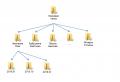
Most of the microcontroller pins are connected to the LCD. Some of them also have a connector for in-circuit programming of the microcontroller (ByteBlaster). Four pins are used in the capacitance measurement circuit, including the comparator inputs AIN0 and AIN1, the output for controlling the measurement limits (using a transistor) and the output for selecting the threshold voltage. A button is connected to the only remaining pin of the microcontroller.
The +5 V voltage regulator is assembled according to the traditional scheme.
The indicator is a seven-segment, 4-digit indicator with direct connection of segments (i.e. non-multiplexed). Unfortunately, there was no marking on the LCD. The same pinout and dimensions (51 × 23 mm) have indicators from many companies, for example, AND and Varitronix.
The diagram is shown below (the diagram does not show a diode for protection against "polarity reversal", it is recommended to connect the power connector through it):
Microcontroller program
Since ATMEGA16 is from the "MEGA" series, and not from the "tiny" series, it makes little sense to write an assembly program. In the C language, it is possible to make it much faster and easier, and a decent amount of flash memory of the microcontroller allows you to use the built-in library of floating point functions when calculating the capacity.
The microcontroller measures the capacitance in two steps. First of all, the time for charging the capacitor through a 3.3 MΩ resistor (lower limit) is determined. If the required voltage is not reached within 0.15 seconds (which corresponds to a capacitance of about 56 pF), the capacitor charge is repeated through the 3.3 kΩ resistor (upper measurement limit).
In this case, the microcontroller first discharges the capacitor through a 100 Ohm resistor, and then charges it to a voltage of 0.17 V. Only after that, the charging time to a voltage of 2.5 V (half of the supply voltage) is measured. After that, the measurement cycle is repeated.
When the result is displayed, a voltage of alternating polarity (relative to its common wire) with a frequency of about 78 Hz is applied to the LCD terminals. A sufficiently high frequency completely eliminates indicator flickering.
From the title of the article it is clear that today we will talk about a device for measuring the capacitance of capacitors. Not every simple multimeter has this feature. But when making another homemade product, we very often think about whether it will work, whether the capacitors that we used are working properly, how to check them. And just in the process of repair, this device will be necessary. You can, of course, check the integrity of an electrolytic capacitor using a tester. But we will find out whether it is alive or not, but we cannot determine the capacity, how dry it is.
Some cheap multimeters on the market today have this feature. But the measurement limit is limited to 200 microfarads. Which is clearly not enough. You need at least four thousand microfarads. But such multimeters are much higher. So I finally decided to buy capacitor capacitance meter... I chose the cheapest one with acceptable characteristics. I opted for the XC6013L:

This device comes in a beautiful box. True, on the box is an image of another multimeter:

And on top is a sticker with the model of this device, probably, the Chinese do not have enough boxes:

The device is enclosed in a protective yellow casing made of soft plastic, similar to rubber. The weight is felt in the hands, which indicates the seriousness of the device. On the underside there is a folding stand, which may not be useful to many:

The capacity meter is powered by a 9 volt krone-type battery, which is supplied in the kit:

The characteristics of the device are simply excellent. It can measure from 200 picofarads to 20 thousand microfarads. Which is quite enough for amateur radio purposes:

On top of the device is a large and informative liquid crystal display. There are two buttons below it. On the left is a red button, with which you can fix the current reading on the display. And on the right is the blue button, which is very pleasing, with the backlit screen, which is undoubtedly a plus of this device. There is a connector between the buttons for measuring small capacitors. True, it is impossible to check the bush capacitors soldered from the donor boards, since the contact pads are located deep enough. Therefore, this connector can be used only by testing capacitors with long leads:

Under the selector for selecting the measuring ranges is a connector for connecting the probes. By the way, the probes are made of the same material as the protective casing of the device, they are quite soft to the touch:

There is also, undoubtedly, the most important function of the device - it is the setting of zero readings when measuring capacities in the picofarad discharge. Which can be clearly seen in the next two photos. Here one probe was deliberately removed and zero was set using the regulator:

Here the dipstick is in place. As you can see, the capacity of the probes affects the readings. Now it is enough to set zero using the regulator and make measurements, which will be quite accurate:

Now let's test the device in operation and see what it can do.
We test the capacitance meter
To begin with, we will check the capacitors that are known to be working, new and removed from donor boards. The first will be the 120 microfarad test subject. This is a new instance. As you can see, the readings are slightly underestimated. By the way, I have 4 such capacitors, and none showed 120 microfarads. Possible instrument error. Or maybe now they are doing one substandard:

Here is one thousand microfarads, quite accurately:

Two thousand two hundred microfarads, not bad either:

And here are ten microfarads:

Well, now one hundred microfarads, very good:

Let's take a look at the meter readings that it will show when checking defective capacitors that were removed during repairs. As you can see, the difference is palpable:


These are the results. Of course, in some cases, an electrolytic capacitor malfunction is visible visually. But in most cases it is difficult to do without a device. In addition, I tested this device on two boards, checking the capacitors without unsoldering them. The device showed good results, only in some cases the polarity must be observed. Therefore, I advise you to buy such a device, and you can measure the capacitance of the capacitors with your own hands.