How to connect the power button to the mat board. Motherboard connection guide. How to connect video cards
FPANEL article - connecting buzzer, Power, Reset buttons, indicator LEDs
On the front panel of the system unitusually there are power and restart buttons, LED indication, multiple USB ports, audio outputs. All of them need to be correct connect to motherboard... This means that, first of all, you need not to break or burn what is still working.
When diagnostics, repair, assembly and disassembly modern computers make mistakes when connecting pin headers to the motherboard quite difficult. The effect of standardization is gradually taking its toll. Manufacturers are trying to unify connectors, making it impossible to connect, for example, wires from external USB connectors to audio contacts.
nevertheless, limiters (including plugs on the contacts) are not on all motherboards, the signatures of the contacts are very small, the connectors are close to each other, and it seems that it is not difficult to make a mistake. Therefore, those who are too lazy to open the manual on the motherboard itself before assembling or connecting additional devices, there is every chance to go to buy a new one or take the old one for diagnostics and repair.
.jpg)
Connection to the F-panel is carried out with special plugs on which the marking is placed. They look something like the picture below.
Accordingly, the same markings are usually applied around the panel itself. Below I will give a decoding of the inscriptions on the wires connected to F_PANEL

Power SW - wire of the power supply button (on / off) of the computer;
Power LED - indicator wire (green LED) power supply;
HDD LED - hard drive operation indicator wire (usually orange or red LED);
RESET SW - wire of the computer restart button;
SPEAKER - wire for a tweeter or miniature speaker inside the case of the system unit.


This option is used by 90% of motherboards. Hard disk drive indicator 1 - 3 pins
Power indicator light 2 - 4 contacts Clear 5 - 7 contacts Power on button 6 - 8 contacts One row turns out all even, the other all odd
The mistake, as a rule, lies in the fact that contacts are established, which is called against the grain. That is, plus for minus, and minus for plus. For buttons, this is usually not important, but the LEDs, I simply will not work, and the speakers, accordingly, beep.
So. Front panel contact block or F_PANEL for short, it is usually located in the lower right corner of the motherboard, although there may be exceptions, but I have not yet met such.
For comparison, I give several pictures with images. F_PANEL from various manufacturers.


.jpg)
.jpg)
Front panel pin headers on motherboards: Asus, Gigabyte, MSI and Nvidia
In general, all connectors are somewhat similar to each other. I mainly come across Asus motherboards and Gigabyte, while giving preference to the latter. In my opinion, they are the best combination of quality and price. 10 years ago, they used more Intel boards.
For many years now, motherboards have been produced, the contact connectors remain unchanged, except that the design and color coding have changed. For the convenience of service services and ordinary users, practically nothing has been done. The only awkward step was made by the firm Asusby releasing a special block. On it, you can, without bending into three deaths with a flashlight above the system unit, connect all the necessary contacts and then stick it into the motherboard.

Why the rest of the manufacturers did not support Asus' idea remains a mystery. It also remains unclear why until now the set of the same contacts in all cases of all system units has not been brought to a single standard, in fact, there is no single standard for motherboards either.
Besides F_PANEL, on motherboards (gygabyte is shown as an example) there are also connectors F_AUDIO and F_USB... The connector pictures are shown below.
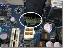


As a rule, on the front panel of the system unit there are interface uSB connectors (usually a couple of them) and ports for connecting headphones / speakers and a microphone. To make a mistake with USB ports, today it has become almost impossible (the shape, the number of pins are less common for all boards and cases), thanks to the manufacturers. With AUDIO connectors, the situation is not so simple, but we are moving towards it.


This standard is mainly used in motherboards, modems, sound cards and cases with front panel audio solutions.

Pin Signal Name Function
1 AUD_MIC Front Panel Microphone input signal Microphone output to front panel
2 AUD_GND Ground used by Analog Audio Circuits Ground, Ground, Minus - whatever you want
3 AUD_MIC_BIAS Microphone Power Something related to the offset of the sound on the microphone, I hope someone will tell you more accurately.
4 AUD_VCC Filtered +5 V used by Analog Audio Circuits 5 Volt power supply for sound
5 AUD_FPOUT_R Right Channel Audio signal to Front Panel Right channel output to front panel
6 AUD_RET_R Right Channel Audio signal to Return from Front Panel Right channel input to the front panel
7 HP_ON Reserved for future use to control Headphone Amplifier Reserved for future use
8 KEY No Pin Goofy contact
9 AUD_FPOUT_L Left Channel Audio signal to Front Panel Left channel output to front panel
10 AUD_RET_L Left Channel Audio signal Return from Front Panel Left channel input to front panel

Usually we have a block or separate contacts with cryptic inscriptions:
1 MIC-VCC, 2 MIC-IN, 3 GND, 4 EAR L, 5 EAR R, 6 LINE L, 7 LINE R
The sound is simple:
6 LINE L to 9 AUD_FPOUT_L
4 EAR L to 10 AUD_RET_L
7 LINE R to 5 AUD_FPOUT_R
5 EAR R to 6 AUD_RET_R
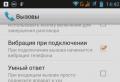
Please note that on some motherboards there will be no sound with installed drivers if there are no jumpers on these pins and the front panel is not connected:


USB contacts
The main thing is not to confuse +5 and GND - these are extreme contacts.
+ 5V is sometimes also denoted as VCC, and the average DATA - and DATA + on all new motherboards, +5 volts is located at the edge of the contact pad, and ground is near an unused contact, as you can see in the picture. On older motherboards (the first on socket 478 and the old socket 370) it occurs when one row is turned 180 degrees.

It remains only to remind the following: before starting to manipulate the equipment - do not be lazy, find or download from the Internet the “operating manual” of the motherboard, today most of the documentation exists in Russian. So the internet will help you, especially google.
When assembling a computer, you definitely need to know how to connect wires to the motherboard, because without this knowledge nothing will work at all. This stage is carried out when all the components are already installed in the case. That is, the motherboard itself, the power supply, the hard drive are in their places. It is also advisable to install the motherboard in the PCI-E slot and screw it to the case. Only now you need to connect the wires to the motherboard. How to do it? We will talk about this now.
How to connect wires to Asus, ASRock, MIS and other motherboards?
It is important to immediately note the fact that the method described below is highly generalized. Different motherboards will connect slightly differently. That is, there may be some differences, but the principle remains the same. Let's start by explaining and connecting the body connectors: power button, reset, USB ports.
Connecting connectors
Before leaving the power supply, you need to connect the connectors to it. It is important to understand here that they are all protected against incorrect connection, so they must be inserted extremely carefully, without any effort.
Please note that each connector is labeled to describe its purpose. The motherboard also has markings, but some models do not. The description of the terminals can only be found in the instructions for the motherboard.
We connect the first connector marked M / B SW. He is responsible for the power button on the case. It may also be called POWER SW. Take a close look at the motherboard (bottom right) for a pair of pins marked POWER. If there is, then it is on them that this connector needs to be fastened. If there is no such inscription, then open the instructions for the board and look for the circuit there.
The second connector labeled RESET SW is responsible for the reset button. By analogy with POWER, we connect the RESET SW connector. If there is no indication on the board, then we look in the instructions for the motherboard which contacts need to be closed.
There are also wires marked POWER LED + and POWER LED-, thanks to which the lamps on the case of the system unit glow. Here it is important to connect them correctly and not to confuse plus and minus. Be sure to check the instructions.
Don't forget about the USB connectors on the case. If you want to be able to insert flash drives into the slots on the case, and not directly into the motherboard, then you need to connect the USB connectors. They are labeled USB. Audi wire is responsible for Jack 3.5 mm, which is used for headphones or speakers.
Let us remind you once again that it is important to know how to connect the power-on wires to the motherboard correctly. And if you have to forcefully stick the connector, then most likely you are doing something wrong. After connecting the wires of the connectors to the motherboard, you can proceed to the power supply.
Connecting processor power

The central processor is placed on the slot allocated for it, and a radiator with a cooler is put on it. No wire is connected to the processor itself. Its power is supplied from the motherboard, and the wire is connected directly to it. The power socket is located next to the processor. See if there is a 4-pin socket nearby. The instructions for the motherboard must indicate its location, but it can be seen even with a cursory examination of the board.
A 4-wire wire is connected to the processor power socket. Usually it is the only one here, so you are unlikely to be able to make a mistake.
Connecting the motherboard main power cable

The largest cable is this one. It consists of twenty connectors (pins), and in addition to it, there are 4 separate connectors. It turns out that the motherboard is connected through 24 connectors. And since the only wire with so many pins comes out of the power supply unit, you cannot make a mistake in determining it. In addition, there is a special latch at the end of the connector that prevents the cable from being inserted into the connector incorrectly.
When plugging in, make sure this structure fits into the socket and snaps into place.

Connecting a video card
If you are using a processor with an integrated video card, then there will be no video card connection. But more often than not, users prefer to use powerful graphics platforms that connect via a PCI-E connector and require additional power.
The video card is powered by a 4-pin connector. The place for food, depending on, may be somewhere on the side, but most often it is located in the back. If the video card is very powerful and demanding on power, then it can be powered from the 6-pin connector. Therefore, when choosing a power supply unit, pay attention to which and how many wires it has for power supply. When plugging in the card, the connector should snap into place - pay attention to this.
HDD connection

The hard drive connects to the motherboard via a SATA cable. On the motherboard (somewhere on the right side) there are usually 4 SATA connectors, where it says: Choose the first one and connect a hard drive to it.
A SATA cable has the same connectors on both ends. But this is not enough. The hard drive also requires power and is usually connected to the chassis via a 4-pin connector. Therefore, connect a four-core cable to it. By analogy, an optical drive for discs is connected, but they are now extremely rarely used.
Connecting RAM
We figured out where to connect the wires on the motherboard, and the fact that the RAM is simply inserted into the connectors and does not require connection through the wires. Your board has 2-4 RAM sockets. Insert the memory there (note, there is protection against incorrect insertion) and press down a little. A click sound will indicate that the memory has fallen into place.
Well that's all, now you know how to properly connect the wires to the motherboard, and you can do it yourself. We add that the developers are trying to make their hardware as convenient as possible for connection. Therefore, you will definitely succeed in assembling this "constructor", because even if you wish, you will not be able to connect the wrong wires to the wrong sockets. There is reliable protection from this.
The case of the system unit is an important component of the entire computer. It is in the case that the “production workshop” of the entire computer is located. It is in the case that the motherboard is installed, and the RAM, video card, processor and all kinds of wires and cables are already "hung" on it. Moreover, the power supply unit is located in a separate place inside the case, however, as well as the hard disk and the drive.Modern cases look quite attractive, menacing, aggressive, unusual ... The developers have enough imagination, which means that ordinary customers can choose from a huge assortment. But not only do the current cases have an attractive appearance, they also have "working" pluses. Such advantages are USB connectors, as well as connectors for a microphone and headphones on the front of the case, which in turn means that every time we need to plug in a USB flash drive, we don't need to climb under the table and get to the back of the case. I think anyone will agree that these are, in principle, trifles, but still, it's more pleasant to just insert a USB flash drive in front and start working.
But, unfortunately, there are times when some parts of the computer case fail. We are talking about the notorious the POWER button, which is absolutely on every case. In the course of long-term operation, this button may simply fail, for example, stop pressing it or vice versa, it will sink into the depths of the case, and no matter how "magic", it will not work to turn on the computer. What to do in such situations? If you do not really need a computer, then it is better to call the master and wait with peace of mind until he repairs everything, paying him a certain amount of money for this.
If you need to use the computer urgently enough, then perhaps you should use the following advice.
To begin with, you need to find a flat surface and carefully put the system unit so that the left cover looks at you, while you should not disconnect all the wires in order to complete everything faster, but it is worth watching so that these wires are not taut. In addition, a prerequisite should be that the computer was disconnected from the power supply, as they say, you never know what. Next, what needs to be done is to remove the left case cover. In modern cases, this usually does not require any great effort, so there should be no problems with this.
After removing the cover, a stunning picture will appear in front of you. You will see all that for which they once gave a round sum, and that usually works peacefully, making an innocent noise, and that now does not want to "start". Our focus should be primarily on the multi-colored wires that run from the front of the case to the motherboard. There can be many such wiring, and it is not surprising, because there are connected and pOWER buttons and rESET button, and USB ports, together with audio outputs. So, in the next step, we may need a little knowledge of English, which many received at school, because on the wiring itself, as well as on the motherboard, near the connection of these wires, it should be written what they mean. Take USB ports as an example. On the motherboard itself, near the connection, there should be an inscription USB1, USB2, etc. This means that the wires connected to these connectors are nothing more than USB connection ports.
But do not forget about our problem, which means that we need to look for pOWER wiring (usually two wires, woven together). Usually the connectors to which the power or reset buttons are connected are located on the lower right side of the motherboard:
On most motherboards, these connectors are the same and consist of 9 pins arranged in two rows. The last two contacts in a short row of 4 plugs are responsible for turning on / off the computer.
Here are the connector diagrams for the most popular motherboard manufacturers.
MSI
AsRock
Asus
Biostar
Epox
Foxconn
Gigabyte
Intel
When these two wires are found, you should find where they are connected to the motherboard. After the connection point has been found, it is worth carefully disconnecting these wiring so that the small plugs are exposed.
Everything, now we have almost done everything. The final step is only turning on the computer, for this we need an ordinary clerical pen, preferably one that writes in bold. After finding such a pen, you can connect the computer to the power supply, and then gently run the tip of the rod over these bare needles. Or in other words, you just need to simply close these contacts... After these steps, the computer should revive, and the download will go. If nothing happened, then it is worth repeating the procedure, but close these needles quickly enough.
Thanks to such simple actions, you can start the computer without any special problems, but you should not neglect this, and it is better to fix the start button on the case as soon as possible in order to avoid unnecessary problems.
Attention: Neither the author of this article, nor the administration of this site, assumes any responsibility for possible problems that may arise during the process of turning on the computer in this way. You will perform all of the above actions at your own peril and risk, and be solely responsible for possible problems that are not described in this article.
It remains to fit one to the other and ... hello, new computer! If there are usually no difficulties with connecting a processor, memory, video card, then the small wiring connecting the contacts of the motherboard with the elements on the case of the system unit makes you scratch your head for a long time: which one leads where?
The pins for buttons, lights, system speaker, and audio connectors all look the same, and each motherboard manufacturer places them differently on their products. Today we will talk about how to properly connect the computer power button to the motherboard and not burn anything.
Front Panel
The area where the power and reset buttons are located, as well as the power indicators, disk activity, sleep and some others on the system unit is called front panel – frontpanel... On the motherboard, it corresponds to the contact group f_panel.

F_panel can look like in the photo, where each contact is painted with a certain color, or it can be solid. The number and location of pins on it is also not the same, so the front panel connection diagram for motherboards, for example, Asus, will not work with Gigabyte motherboards and vice versa.
On some motherboard models, the front panel contacts are signed, which greatly facilitates the assembly of the system unit.

But most often they are simply marked with serial numbers, as in the first photo. In this case, you cannot do without instructions.
Power button
From the power button on the front panel of the system unit 2 wires leave, which end in a rectangular connector with two holes and the inscription “ POWERSW "(Power switch). Do not confuse it with the " POWERLED”, The latter is for connecting the computer's power indicator.

The "POWER SW" connector connects to a pair of pins on f_panel, which are labeled in the same way on the wiring diagram. In some circuits, the Power switch is indicated as PSW,PWR, PWRBTN, PWRSWor ON /OF.
The front panel contacts have polarity, that is, one of the pair of conductors is connected to the "+" pin, and the other to the "-". The Power switch connector also has a minus and a plus, but it can be connected to the motherboard by either side, since it works to close / open the circuit.
What happens to your computer if you mistakenly connect the power button to a different connector, such as indicators or the system speaker? It's okay - it simply will not start, since the switching circuit, which is closed by pressing the button, will remain open.
Likewise, you should not be afraid of problems if you make a mistake with connecting other elements of the front panel. An incorrectly connected element simply won't work.
How to connect the power button on boards of different brands
Asus

- On Asus boards with a 10-pin front panel connector, the PWR BTN pins are in the middle (pins 5 and 6).
- On boards with a 20-pin connector, they are located on pins 11 and 13.
AsRock

Different models of AsRock motherboards have different arrangement of Power switch contacts. For instance:
- On a 10-pin connector: pin 5 and 6 or pin 6 and 8.
- On a 20-pin connector: pin 6 and 8.
Gigabyte

Gigabyte's front panel connectors most often have 20 pins. The power switch has pins 6 and 8.
Biostar

Biostar motherboards are not very common in our country, but models with the following PWRSW pin arrangement are more common:
- On 16- and 24-pin connectors - 14 and 16 pins or 15 and 16 pins, if the contacts are counted in horizontal rows.
- The 10-pin connector has 6 and 8 pins.
MSI

On MSI boards, the f_panel connector has 10 pins, the Power switch pins are numbered 6 and 8.
Fujitsu Siemens

On the 30-pin Fujitsu Siemens front panel, the Power On / Of pins are ranked 25th and 26th. Please note that contacts on this board are counted from right to left.
Foxconn

- Foxconn motherboards have a 20-pin power switch pin 6 and 8.
- On a 10-pin group - also 6 and 8.
Epox

On Epox products with a 20-pin front panel connector, the Power button is connected via pins 11 and 13.
Intel

Another exotic motherboard brand is Intel, available in 10- and 12-pin f_panel groups. The power button is wound on pins 6 and 8.
Lenovo

- On Lenovo motherboard models with a 14-pin front panel connector, the power button is connected to pins 9 and 11.
- On 10-pin models, the Power switch is assigned to pins 6 and 8.
Here are collected only the most common options for connecting the Power button to the motherboards of desktop computers. If none of them suits you, "feed" the search engine a query: "model_of_your_board front panel connection" and see the found pictures. Most likely, the answer will be found very quickly.
When assembling a PC, one of the most important parts is connecting the case to the motherboard (or system) board. It is important because, no matter how powerful and expensive a PC, it will remain just a piece of furniture if it cannot be turned on.
It is on the case that all the vital controls and indicators of the PC health are located. Correct connection of buttons and indicators will allow the user to control the operation of the PC and receive, albeit simple, but reliable confirmation of its correctness.
Of the controls located on the case, one of the most important is the computer power button, or the power switch.
Often, the locations of the connection points for certain switches and indication means may differ depending on the selected computer components. Moreover, this may depend not only on the manufacturer, but also on the specific model of a particular unit as part of a PC.
This article will show you how to connect the power button to your motherboard.
Preparing to connect
To correctly connect the power button to the motherboard, a number of preparatory work should be carried out, as well as the necessary tools should be prepared.
Important! The latter circumstance should not be ignored, since the design features of some motherboards do not allow making connections using only fingers.
Preparatory work consists in familiarization with the instructions for the motherboard. If the manual was not included with it, knowing the model of the device (and it is always written on it, most often near the edge or in the middle, between the expansion slots), you can find its electronic version on the Web. The instruction will indicate the location of the front panel mini-connector and show the layout of its outputs in the absence of inscriptions on the motherboard.
Of the tools you will need:
- small tweezers (to hold the connector from the system unit when installing it);
- screwdriver with PH1 bit (in order to provide access to the front of the case, if the need arises).
How to connect the power button to the motherboard in stages
The instructions for connecting the power control circuit are as follows:
- On the motherboard, you should find a system mini-connector, as a rule, representing two rows of pins, 10-12 in each, with characteristic inscriptions. Most often, this connector is located in the lower right corner of the board.
- Find the location of the power switch on the connector.
- In the case (often near the front panel), you should find wires with connectors for connecting indicators and various switches and choose the power-on connector among them.
- Connect the power-on connector from the PC case to the mini-connector pins on the motherboard.
In order not to be mistaken with the designation of the "legs" of the connectors, let us consider the typical ways of their designation on modern components.
Button and LED connector conventions
Directly next to each group of contacts of the mini-connector (the so-called "pins" from the English "pin"), which perform a specific function, a description of their purpose is given. This is done so that PC assemblers are not mistaken, since there is no single standard for the arrangement of mini-connector contacts.
Attention! Often the functional purpose is not only described, but also duplicated by the color of the plastic part of the connector. For display devices, polarity is also indicated.
The following designations are used:
- POWERSW, POWER SWITCH, PSW, PSWITCH - pins of the power button connector;
- RESET, RESETSW, RST, RESTART - pins for restarting the computer;
- POWERLED, PWLED, PLED, POWERON, PON - pins for indicating the presence of electrical power (operability or turning on the PC) on the motherboard;
- HDDLED, HDLED, HLED - hard disk access indication outputs;
- SPEAKER, SPK, SPEAK - pins for connecting a system speaker.