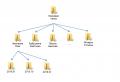
Interesting examples for arduino multi function shield. We make a programmer shield for the Arduino Uno lying around. Everywhere has its own specifics, shields for unusual tasks ...
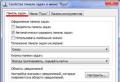
The Arduino is a tiny board with a lot of features, a typical Open Hardware representative and one of the first devices to gain widespread popularity among hardware hackers. No wonder: a convenient electronic construction kit allows even beginners to quickly figure out and start from scratch to develop their own devices.
How to get started quickly?
For a quick start, the easiest way for a beginner is to buy a ready-made board - it costs about $ 30. There will be only two chips on the board - an ATMEL microcontroller and a USB interface chip to which it is connected. All other elements are added independently as needed.
Arduino programs (called "sketches" in slang) are written in the Wiring language. In fact, this is ordinary C ++, extended with special procedures like "digitalWrite" (write a value to the port) or "analogRead" (read a value from the ADC). All this is mastered in one or two sessions, especially if you already have experience in programming in C ++. The written sketches are compiled and uploaded to the Arduino via USB using the ArduinoIDE environment (arduino.cc/en/Main/Software). It takes about thirty minutes to assemble the simplest project, without the need deep dive into ATMEL datasheets and assembler constructs. The language is intuitive, and a good online help will help to deal with the nuances. And soldering, by the way, is also optional if there is a solderless breadboard and a set of wires.
All pins of the microcontroller are displayed on two neat rows of pads, to which you can connect sensors, buttons, displays, and the like. However, the more complicated the strapping, the more hemorrhoids can be with it. If it comes about a couple of LEDs and buttons, then no complications. But if you need to control motors or exchange data via a radio interface, a number of difficulties arise. To combat this flaw, they came up with shield boards - ready-made boards for expanding functionality.
What is a Shield Board?
Shield-board is a ready-made solution for the implementation of frequent tasks faced by hardware developers. Examples of such tasks can be data transmission via the radio interface, and work with Ethernet, and control of electronic motors. Expansion boards are easy to install on the Arduino, joining the pin pads and forming a very rigid sandwich-like structure.
You can install several boards at the same time, the main thing is that the devices do not conflict for the same Arduino pins. After a little digging on the net, you can find tables with a list of popular shields and their pins (shieldlist.org).
Then it remains only to hook up the corresponding library to the main sketch and test the operation of the circuit using the example sketch attached to the library. With this approach, time is saved twice: first on the development and debugging of the hardware, and then on the software. However, there are only a couple of dozen truly successful and popular shield boards. How is a good shield different from a bad one?
First of all, it must have a reset button. Anyone who has debugged an Arduino with a shield dressed can appreciate this - the standard reset button becomes inaccessible and the exercises for pressing it with the help of improvised oblong objects are annoying. A good shield should also be compatible with the Arduino Mega - if you have an extended version of the Arduino with an ATmega1280 or ATmega2560, it is not a fact that a shield made for the familiar Uno or Duemilanova will work with it. And all due to the fact that in Mega, the pins responsible for the hardware SPI were moved to another place! So if the shield communicates with the Arduino via the SPI bus, be sure to examine its "belly" - you can hope for compatibility with Mega if you see there not only pins, but also a black square 2x3 female connector. Below I have prepared a review of the best ready-made Shield boards for solving common tasks.
Motor control
If you need to control motors, feel free to use the Motorshield shield, created by the talented American engineer Limor Freed aka ladyada (ladyada.net/make/mshield/).
The main advantage of the shield is its versatility as it supports up to four direct current motors, up to two stepper motors and two servo drives. Can be combined: for example one stepper and two DC motors. The basis of the shield is provided by two L293D quad H-bridge microcircuits, capable of delivering current up to 600 mA per channel and operating at voltages from 4.5 to 36 V. By parallelizing the inputs of one microcircuit, you can push the current limit to 1.2 A.
With this shield it is possible, for example, to simultaneously control the motors and the steering rod of a racing car model, the stepper motors of the coordinate table. For more powerful loads, you can use Ardumoto with the L298 chip from Sparkfun (two channels with load currents up to 2 A) or its more advanced version Monster Moto Shield (sparkfun.com/products/10182) on two VNH2SP30 chips, capable of delivering up to 30 And with a maximum voltage of 41 V. If it comes to the last option, do not forget to consult with knowledgeable specialists: after all, the loads are pretty decent, you may have to get an additional radiator so as not to burn yourself.
Working with Ethernet
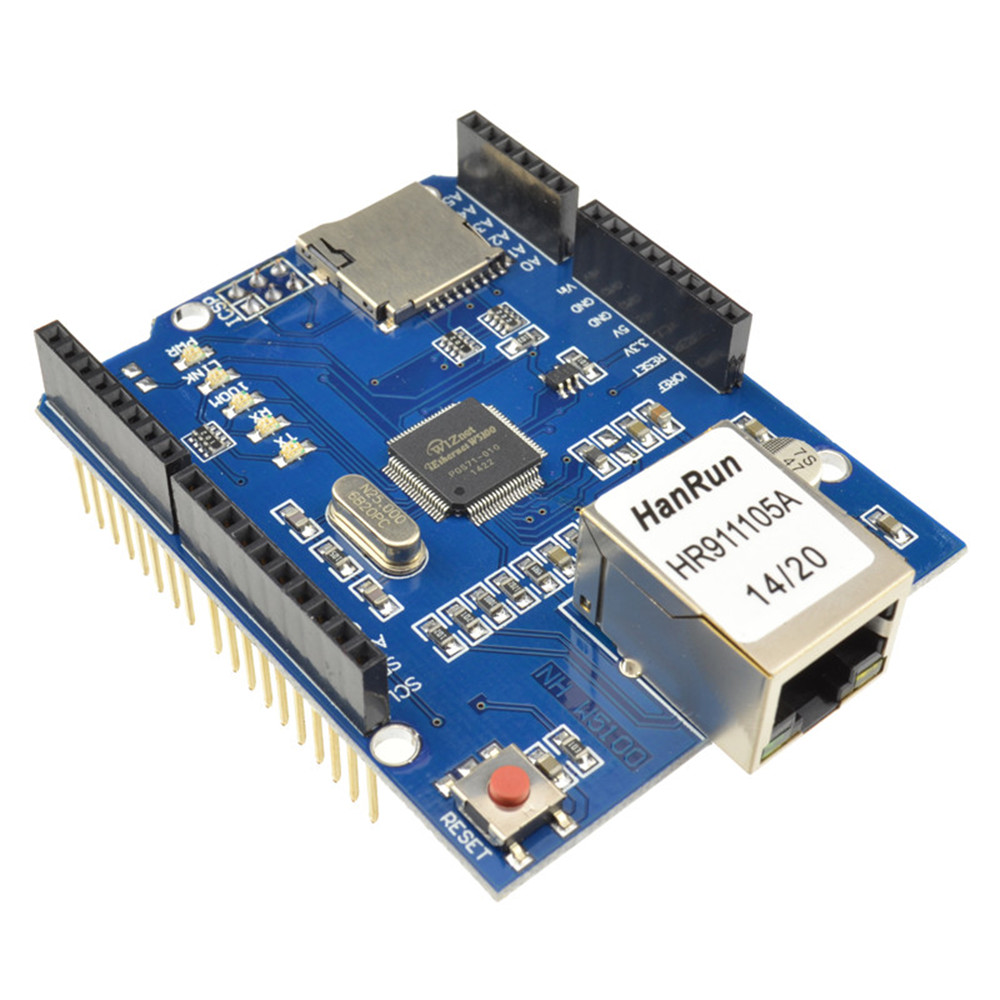
There are two main options for Ethernet shields - based on the good old ENC28J60 chip from Microchip and the more advanced W5100 from Wiznet. Both solutions use the SPI bus for communication, taking away only four Arduino pins. But ENC28J60 appeared much earlier and clearly loses to the advanced W5100: only 10 Mbps, no hardware support for IP, UDP, TCP. In addition, the W5100 supports four sockets (which means support for up to four concurrent connections).
In general, I strongly recommend using the W5100, because it significantly saves the key resource of the microcontroller - rAM (SRAM), which has to be saved (Atmega328 has only one kilobyte). Well, all the other advantages of preprocessing are obvious: while the W5100 itself asks for packets via TCP and calculates the header checksums, Atmega can calmly do more important things.
Another example is the Arduino Ethernet Shield (arduino.cc/en/Main/ArduinoEthernetShield) from the Arduino team. With its help, you can create a sketch that will be able to:
- get dynamic IP address via DHCP;
- set the time using the NTP protocol;
- resolve names via DNS;
- pass authorization via RADIUS;
- act as a simple Web server; or act as a Web client, making requests and parsing responses.
Among similar boards, one can note the development of Freetronics - EthernetShield with PoE (freetronics.com/products/ethernet-shieldwithpoe). The idea of \u200b\u200bpowering an Ethernet device from the same Ethernet line to which it is connected was born in 2001 and two years later became the official industry standard IEEE 802.3af. From my own experience, I note that there is nothing more convenient for powering self-contained boxes that communicate via Ethernet and are scattered around the building within a radius of 100 meters from a special power switch. Such a shield costs a little more, requires the purchase of an additional microboard for the PoE module and has a breadboard instead of an SD slot.
The use of such a shield is exclusively in fixed structures that require interaction with tCP networks/ IP. For example, displaying the status of connected sensors in the browser or remote control some mechanisms.
Immediately I remember the "twitter flower" project, in which the Arduino + Ethernet bundle with the help of a humidity sensor stuck into the ground through twitter complained of dryness and required immediate watering. With all the variety of EthernetShield applications, I want to warn you that each library certainly saves time, but it also takes several kilobytes of the microcontroller's flash memory. Therefore, if sooner or later you run into the 30 KB limit of your Arduino Duemilanova - think about replacing it with a Mega 2560, the memory for sketches will be eight and a half times more.
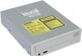
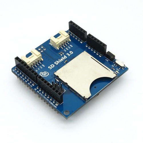
Using SD Cards
In projects related to the accumulation of any information (for example, GPS coordinates), it is often required to increase the amount of available non-volatile memory. The easiest way to do this is by connecting a standard SD card. There are several ready-made shields for this. The nicest option I know of is the microSD module, developed by the Spanish company Libellium, which specializes in environmental monitoring (goo.gl/iHCy4).
The shield takes up just one Arduino pin header and allows you to work with SD and SDHC cards pre-formatted to FAT16 (preferred) or FAT32. You can work with only one file at a time, long names are not supported.
Wireless shields
The simplest RF modules on amplitude modulation (ASK), operating in the unlicensed 433 and 313 MHz range, although they can be used with Arduino through the VirtualWire library, still seem to me a rather bad option.
They are too susceptible to interference, they only work stably on low speeds, do not have hardware separation into channels - several simultaneously operating transmitters will interfere with each other. Perhaps that is why I have not yet seen a shield board for them.
The polar opposite is the Xbee family of cards based on Zigbee protocols, ideal for organizing distributed sensor networks self-powered. Each such board is itself a device with a microcontroller on board, and very little is required from the shield - to ensure coordination with the Arduino. Such shields are usually called "Xbee Shield", but not always - for example, Libellium developed Communication Shield (goo.gl/OZDxl). The shield necessarily contains two rows of pads, to which the module in Xbee format is docked.
The only drawback, perhaps, is the price of the Xbee module itself. In return, we get a speed of up to 250 Kbps, a line-of-sight range of up to 90 meters (the Xbee PRO modification can reach up to 1.2 km), encryption, economical power consumption and the ability to relay data (two modules transparently communicate with each other through the third).
It has long been noticed that if a company comes to talk about wireless networks, first of all for some reason they remember about WiFi, much less often - about Bluetooth. SparkFun's WiFly Shield (sparkfun.com/products/9954) and Libellium's Bluetooth module (cooking-hacks.com/index.php/arduinobluetoothmodule-89.html) are good examples. The latter is made in Xbee format and will work with any transitional shield for Xbee, and software setting from Arduino resembles dialogue with a modem - through the serial port and AT commands. By the way, at one time, the original Arduino BT board (arduino.cc/en/Main/ArduinoBoardBluetooth) was released, which did not have a USB interface, but was programmed and connected to the computer via Bluetooth. She did not receive wide distribution - perhaps due to the increase in price.
To exchange data via GSM, a mobile phone is usually used that can work over a serial port at TTL levels.
But now there are fewer and fewer of them - they are being superseded by USB, which requires being a host (and not a device, which is an Arduino) to work with. But, fortunately, manufacturers have been churning out finished GSM modules for a long time, to which it remains to turn the external antenna and SIM card connector. You don't have to look far for an example - the GPRS Quadband module for Arduino from Libellium (goo.gl/KueFH), which is based on the GPRS modem from SAGEM.
A feature of this particular model is that the GRPS module is removable, and you can transfer not only data - the output to an external speakerphone is divorced.
Different shields
Summing up a brief summary, we can say with confidence that solutions to almost all typical problems have long existed in the form of shields. But don't think that this is where it all ends. Here are some examples: Radiation Sensor Board from Libellium (Geiger counter).
DIY Shield
As an example, let's create our own LCD shield. The connection diagram of the popular 1602 alphanumeric LCD display on the HD44780 controller is possible in two versions - an eight-bit bus or a four-bit bus. It's time to open up the Arduino shield building strategy: there are never too many pins! We try to use them to a minimum and therefore choose a four-bit scheme (fortunately, support for such a scheme is included in the ArduinoIDE distribution, in the form of the LiquidCrystal library).
To build our shield, we use a special blank - a protoshield, which is a prototype board with a few tweaks. Its most important value is the correctly spaced pin holes for perfect docking with the Arduino. It just so happened that all the pins of the pins are located on a grid with a pitch of 2.54 mm, except for one (if not for this annoying fact, one could take any piece of the "perforated layout" and solder PLS docking plugs into it). This was done on purpose so that the recipient, out of absent-mindedness, would not insert the shield backwards and burn the future masterpiece in the bud.
Please note that the circuit provides a variable resistor to adjust the contrast. It is important! If you forget about this, if the rest of the scheme is correct and the sketch is correct, nothing will be visible. Any 10-20 kOhm is suitable, and specifically on this protoshield it is already provided for - although it is connected to the analog0 input, so you have to solder the extra wiring.
Take a piece of the PLS pin comb and solder it first to the display pins, and then to the shield. After that, you need to take the mounting wire and carefully, in turn, strip and solder the wiring from the display to the Arduino pins according to the diagram - fortunately, it is simple. I intuitively managed to hide most of it under the display.
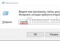
Let's put the result on the Arduino and load the first test sketch from the LiquidCrystal catalog. Is there nothing on the screen? Or a bunch of black squares? It doesn't matter, it's time to tighten up the variable resistor - I'm sure something will definitely appear! In this case, you can breathe a sigh of relief - now you have your first custom-made shield. Well, since it has worked, you can Russify it at the same time. At one time, I changed the standard library so that Cyrillic characters are correctly translated from UTF-8 to the display character generator. Look for latest version libraries at github.com/mk90.
Flashing an LED and the like is certainly great, but I wanted to do something really more or less worthwhile that can be used in everyday life. Probably the simplest thing is to turn on and off powerful current consumers - light bulbs, ve cleaners, pumps, tape recorders, etc. For this, Relay-Shield will help us. There are ready-made solutions, a bunch of schemes on the internet. But it's more pleasant to do it yourself.
Here. Now you can start sealing the components. First of all, jumpers and small elements (resistors, diode assembly, transistors).
The most troublesome thing is to seal the connector pins .... But, somehow I managed it :) So you can too. The main thing is that there would be no "snot", "short stacks" and "non-stop" :)
Here are some photos of the finished product. Let's just say, not an exhibition option, but still ...
By the way, SMD diodes are visible from below, standing parallel to the relay windings. The transformer is secured with two wires.
And fill in the test skate:
/*
Test Home made rele Shield (Ghost D. 2012)
We use digital pins # 7 and # 8
*/
void setup () (
//
pinMode (7, OUTPUT);
pinMode (8, OUTPUT);
}
void loop () (
digitalWrite (7, HIGH); // Turn on the first relay
delay (2000); // we wait
digitalWrite (8, HIGH); // Turn on the second relay
delay (2000);
digitalWrite (8, LOW); // Turn off the second relay
delay (2000);
digitalWrite (7, LOW); // turn off the first relay
delay (2000); //
}
Our new shield clicks its reels. Voila !!!
P.S. In my version, during testing, the transformer heats up quite strongly. Either the information (like 300 mA) was incorrectly indicated on the power supply unit (where I got it from), or there is some kind of trouble with it ...
One of the key benefits of the Arduino platform is its popularity. The popular platform is actively supported by manufacturers of electronic devices that release special versions of various boards that expand the basic functionality of the controller. Such boards, quite logically called expansion boards (another name: arduino shield, shield), serve to perform a wide variety of tasks and can significantly simplify the life of an arduino player. In this article, we will learn what an Arduino expansion board is and how it can be used to work with a variety of Arduino devices: motors (motor driver shields), LCD screens (LCD shields), SD cards (data logger), sensors (sensor shield ) and many others.
Let's first understand the terms. The Arduino Expansion Board is a complete device designed to perform certain functions and connected to the main controller using standard connectors. Another popular name for an expansion board is the English Arduino shield or just a shield. All the necessary electronic components are installed on the expansion board, and interaction with the microcontroller and other elements of the main board occurs through the standard arduino pins. Most often, the shield is also powered from the main arduino board, although in many cases it is possible to power it from other sources. In any shield, there are several free pins that you can use at your discretion by connecting any other components to them.
The English word Shield is translated as a shield, screen, screen. In our context, it should be understood as something that covers the controller board, which creates an additional layer of the device, a screen behind which various elements are hidden.
Why are arduino shields needed?

It's very simple: 1) so that we save time, and 2) someone was able to make money on this. Why waste time designing, placing, soldering and debugging what you can take already in the assembled version, immediately starting to use? Expansion cards that are well thought out and built on quality hardware are generally more reliable and take up less space in the end device. This does not mean that you need to completely abandon self-assembly and you do not need to understand the principle of operation of certain elements. After all, a real engineer always tries to understand how what he uses works. But we will be able to make more complex devices if we do not reinvent the wheel every time, but focus our attention on what few people have solved before.
Naturally, opportunities come at a price. Almost always, the cost of the final shield will be higher than the price of individual components, you can always make a similar option cheaper. But here it is up to you to decide how critical the time or money spent is for you. Taking into account the feasible help of the Chinese industry, the cost of boards is constantly decreasing, so most often the choice is made in favor of using ready-made devices.
The most popular examples of shields are expansion cards for working with sensors, motors, LCD screens, SD cards, network and GPS shields, shields with built-in relays for connecting to the load.
Arduino Shields connection
To connect the shield, you just need to carefully "put" it on the main board. Usually, the pins of the comb type shield (dad) are easily inserted into the connectors of the arduino board. In some cases, it is necessary to carefully correct the pins if the board itself is not soldered neatly. The main thing here is to act carefully and not use excessive force.
As a rule, the shield is intended for a very specific version of the controller, although, for example, many Arduino Uno shields work quite well with Arduino Mega boards. The pinout of the contacts on the mega is made in such a way that the first 14 digital contacts and the contacts on the opposite side of the board coincide with the location of the contacts on the UNO, so the shield from the arduino easily becomes into it.
Arduino Shield programming
Programming a circuit with an expansion board does not differ from the usual arduino programming, because from the point of view of the controller, we simply connected our devices to its usual pins. In the sketch, you need to indicate those pins that are connected in the shield with the corresponding contacts on the board. As a rule, the manufacturer indicates the correspondence of the pins on the shield itself or in separate instructions by connection. If you download the sketches recommended by the board manufacturer itself, then you won't even need to do this.
Reading or writing of shields signals is also done in the usual way: using functions, and other commands familiar to any arduino player. In some cases, collisions are possible when you are used to this connection scheme, and the manufacturer chose a different one (for example, you pulled the button to the ground, and on the shield - to the power supply). You just need to be careful here.
As a rule, this expansion card comes in arduino kits and therefore arduino users are most often found with it. The shield is quite simple - its main task is to provide more convenient options for connecting to the Arduino board. This is done using additional power and ground connectors brought to the board to each of the analog and digital pins. Also on the board you can find connectors for connecting an external power supply (to switch you need to set jumpers), an LED and a restart button. Shield variations and examples of use can be found in the illustrations.


There are several versions of the Touch Expansion Board. They all differ in the number and type of connectors. The most popular versions of Sensor Shield today are v4 and v5.
This Arduino shield is very important in robotic projects because allows you to connect normal and servo motors to the Arduino board at once. The main task of the shield is to provide control of devices that consume a current high enough for a conventional Arduino board. Additional features the board is the function of controlling the motor power (using PWM) and changing the direction of rotation. There are many types of motor shield boards. Common to all of them is the presence in the circuit of a powerful transistor through which an external load is connected, heat sinks (usually a radiator), circuits for connecting external power, connectors for connecting motors and pins for connecting to an arduino.


Networking is one of the most important tasks in modern projects. To connect to local network via Ethernet there is a corresponding expansion board.


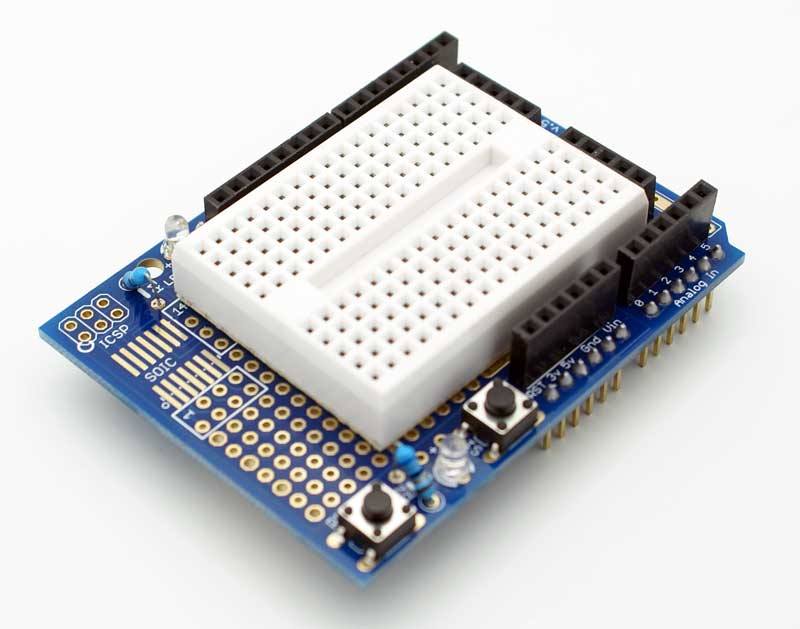
Expansion boards for prototyping
These boards are quite simple - they have contact pads for mounting elements, a reset button is displayed, and there is the possibility of connecting an external power supply. The purpose of these shields is to increase the compactness of the device, when all the necessary components are located immediately above the main board.


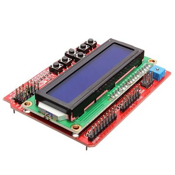
Arduino LCD shield and tft shield
This type of shield is used to work with LCD-screens in arduino. As you know, connecting even the simplest 2-line text screen is far from a trivial task: you need to correctly connect 6 screen contacts at once, not counting the power supply. It is much easier to insert the ready-made module into the arduino board and simply upload the corresponding sketch. In the popular LCD Keypad Shield, from 4 to 8 buttons are immediately connected to the board, which allows the device to organize an external interface for the device user. TFT Shield also helps


Arduino Data Logger Shield
Another task that is quite difficult to implement independently in your products is storing data received from sensors with a time reference. The ready-made shield allows not only to save data and receive time from the built-in clock, but also to connect sensors in a convenient form by soldering or on a circuit board.


Brief summary
In this article, we have reviewed only a small part of the huge assortment of all kinds of devices that extend the functionality of Arduino. Expansion boards let you focus on the most important thing - the logic of your program. The creators of the shields have provided for correct and reliable installation, the required power supply. All that remains for you is to find the desired board using the coveted English word shield, connect it to the arduino and download the sketch. Usually, any programming of the shield consists in performing simple actions to rename the internal variables of the already finished program. As a result, we get ease of use and connection, as well as the speed of assembly of finished devices or prototypes.
The disadvantages of using expansion boards are their cost and possible loss of efficiency due to the versatility of shields, which lies in their nature. For your specific task or end device, all of the shield functions may not be necessary. In this case, you should use the shield only at the stage of prototyping and testing, and when creating the final version of your device, think about replacing it with a design with your own circuit and layout type. It's up to you, you have all the possibilities for making the right choice.
As a rule, acquaintance with the Arduino hardware platform begins with connecting the simplest peripherals: LEDs, buttons, buzzers, etc. Usually for this, the circuits are assembled on a breadboard, but another option is possible. There is a commercially available shield on which the most widespread simple peripherals are already assembled. This multifunctional shield was purchased on Ali for $ 2.

The device is shipped in an antistatic bag. The module has dimensions 69 x 53 x 20 mm, weight 24.4 g.

The device is designed for joint work with Arduino UNO, Arduino Leonardo and Arduino Mega boards, although, of course, using wires you can connect this device to any board of the Arduino family. However, the latter does not seem rational to the author of this review, since in this case the main advantage of this board is lost - ease of installation.

It should be noted that when installing this board on top of the classic Arduino UNO, the board rises with a slight skew, the reason for this is the rather large USB-BF connector on the Arduino UNO board. Of course, the Arduino Leonardo won't have this problem. However, this did not affect the work of this shield.


There are 4 seven-segment indicators on the board, switched on through 74HC595 shift registers, next to which there is a reset button and an APC220 connector for connecting Bluetooth modules or a voice module.

In addition, the board has four red LEDs connected to ports D10, D11, D12, D13 of the Arduino board. The buzzer is connected to port D3, it should be noted that the sound emitter is equipped with a built-in generator, so it will not work to reproduce a simple melody with its help. At the bottom of the board is a trimmer connected to port A0.
Three buttons connected to ports A1, A2, A3 ( digital ports D15, D16, D17, respectively). Four three-pin connectors are connected to ports D5, D6, D9, A5 and are intended for connecting external devices... The list of devices is completed by a connector for connecting analog LM35 or digital DS18B20 temperature sensors. The sensors are connected to port A4. Jumper J1 connects or disconnects the 10 kΩ resistor for correct work sensors
Controlling LEDs and sound emitter is no different from controlling any simple digital device... For example, you can blink the LEDs and sound the buzzer using the port_D program.

Working with a potentiometer can also be described by the classic example of AnalogInput, which, using a variable resistor, controls the blinking frequency of the LED connected to port D13.

You can try to control the LEDs using the buttons, for this you need to download the program _3_LED_with_button
Seven-segment displays are a powerful visualization tool, keep in mind that if they are not used, they will display random characters.

You can check their performance using the program _7seg

In principle, based on this shield, without any hardware modifications, you can collect various timers, for example, the Count_Down_Timer countdown timer. The timer allows you to set time intervals from 10 sec to 60 min 50 sec in 10 sec increments. In this timer, the A2 button sets the minutes, the A3 button sets the seconds, and the A1 button starts the countdown. At the end of the preset time, an audible signal sounds.

Overall, the shield leaves a favorable impression. This device not only allows you to get acquainted with the basic Arduino, but can also become the basis for a simple project, such as a timer, an event counter, etc. Naturally, the reverse side of trying to fit the maximum of the periphery on the shield is that in each specific project some of the device's parts will not be used.
It may seem that such a primitive periphery will be relevant only for learning at the initial stage. This is partly true. Of course, problems with connecting several buttons, LEDs, a buzzer or a seven-segment indicator to the Arduino board can only arise from a person who with a soldering iron on You... Any more or less experienced radio amateur is unlikely to have a problem with this.
Here the question is different, if the goal is to create a prototype of a device in the shortest possible time, then unnecessary trivial operations are exactly what actually distracts from creativity. In fact, this shield fits into the ideology of buying amenities and your own free time for money.
useful links
- http://radioskot.ru/blog/raspinovka_usb_i_micro_usb/2013-09-11-97
- http://publicatorbar.ru/2017/12/21/arduino-multi-function-shield/
- http://robocraft.ru/blog/arduino/59.html
- https://www.youtube.com/watch?v\u003d_z263RK31QA
Review prepared by Denev.
DIY "Shield"
This article will show you how to make your own "Shield" for board Arduinousing a solderless breadboard.

Required components
- Small Solderless Breadboard (Digikey 923273-ND)
- Small PCB (Radio Shack 276-150)
- Two simple 8 -pin scallop (Jameco 70755 or Digikey AE10048-ND)
- Two 8 -pin single row wrap-around scallops (Jameco 78642 or Digikey S7006-ND)
Steps
- We take the printed circuit board.
- We take the combs for wrap mounting, insert them into the outermost row of holes on the PCB and solder them.
- We insert simple combs next to the combs for wrap mounting. We solder them.
- We shoot protective layer with double-sided adhesive tape on the breadboard. Glue the breadboard to the PCB next to the soldered combs.
- Carefully bend one row of contacts for wrap-around installation towards another of the same row. This must be done because the distance between the two combs is Arduino does not match step 2.54 mmlike a printed circuit board. Yes very sorry.
- Done! The final product looks something like this:

On the PCB, two rows of pins are connected to each other, so there is no need to use wires to connect these rows to each other - simple soldering is sufficient.

You can apply some glue to the opposite corner of the PCB to balance the combs and keep the PCB level.
Using
The "shield" we assembled is one-sided, so it can be connected to the board so that its top side remains open.

However, "Shield" can be connected in the traditional way, as shown in the very first picture to this article. In this form, access to the power connector and analog contacts does not cause any special problems, but the reset button and ICSP- the scallop is harder to get. Oh, and it all took me about 10 minutes of work.