Samsung 3205 firmware via debug cable. Restoring the printer using a debug cable. Step: Connecting the debug cable to the formatter board


![]()

Debug cable (USB debug) - serves to restore the FW firmware of a printer or mfp, most often after an unsuccessful firmware.
Causes of FW printer malfunction:
1. In the process of flashing the device, the connection was interrupted: the electricity was turned off or the device hung up or the USB cable was disconnected.
2. An “incorrect” FW was written by mistake, not corresponding to the model of the device or version.
3. In the case when, one hardware non-upgradeable (NU) firmware was uploaded and an error was made in serial number (in this case, the MFP works normally, but without a chip, an error is issued and the device does not work).
4. Warranty case device breakdown with FW malfunction. In cases of updating via the Internet, although the Smart-panel warns that during this procedure you cannot turn off the computer or the device.
What is the essence of the procedure for flashing the device with a Debag cable? If the MFP is not detected by the computer, then you cannot fill FW into it, for this you need to connect to the board through the service connector and, commanding through the Hyper Terminal, force the bootloader to start so that the device is detected in the computer and can receive FW via USB port.
Advantages of the offered USB debug lanyard:
Works on the USB bus - can be used on mini computers - type no-beech. When the device is operating, there is a light indication for receiving and transmitting data. Convenient connector for connecting to the service connector of the MFP.
Everything is included: detailed instructions, software, drivers, original firmware.
Similar free ads on the site:
| Office paper А 4, class "C", brand "Snegurochka", 80 g / m2, 500 sheets, 5 packs per pack. production: Syktyvkar, whiteness 146% (CIE), in addition, in ... | |
Why recovery is needed samsung firmware debug with a cable? This article is helpful if you have failed to flash the Samsung scx-3405, SCX-3400 or scx-407 MFP. An indication of incorrect firmware is that the MFP does not print reports. In this case, it will not work to restore the factory firmware without a debug cable.
Debug cable connection
As a debug cable, a cable for a NOKIA phone is suitable. It has a USB connector on one side and three wires TX, RX and GND on the other. To connect to the main board of the printer, you need to remove the side cover of the MFP and solder to the board, as shown in the photo. On the other side of the board, in the same place, there is a place where there is a special place for a jumper. Without this jumper, data will not be transmitted.
After connecting the cable to the computer via the USB connector, you need to install the cable drivers for another COM to appear. Through this virtual COM, the printer will be controlled. If the COM port does not appear in the device manager in the ports, then the drivers are not installed correctly. Without drivers, nothing will work. Make sure the drivers are installed correctly.
Then we connect the computer to the printer with a USB cable and install the printer driver. Then we install this printer by default. It will not print, but it is not necessary.
Restoring Factory Firmware
Unpack the archive and launch Terminal. We check the COM ports there, select the newly appeared one and configure it as follows:
- baud rate - 9600 or another up to 115200;
- data bits - 8
- parity - none;
- stop bits - 1;
- handshaking - none.
Then press the N key and turn on the printer. Data exchange with the printer will start, at the end it will ask you if you want to start downloading from an external port and the inscription vxshell\u003e. Enter fl in small letters. Again, the data exchange and the ready to download prompt ... This means that the MFP is ready to accept the new firmware.
In this article, I'll show you how to put together a debug lace effortlessly.
We will collect according to this simple scheme:
We need:
- Microcircuit MAX232 - 1pc.
- Capacitor 0.1 μFt - 4 pcs.
- Resistor 50 Ohm - 2 pcs.
- Mother of the COM port (aka DB9) and the case for it - 1 pc.
- And a piece of USB cable.

So, let's begin:
We solder the first capacitor to 1 and 3 legs of the microcircuit.

We solder the second capacitor to legs 4 and 5.

The diagram shows that two more capacitors from 2 and 6 legs are soldered to the ground, and since the 15th leg of the microcircuit is also soldered to the ground, we simply solder the capacitors from the 2 and 6th legs to the 15th leg.
Like this from 6 legs

And like this from 2 legs

We take a piece of wire (I take it from the USB cable) and pull out one wire from it, clean the remaining wires from insulation on both sides.

As you can see from the diagram, we need only three contacts from the COM port, namely 2, 3 and 5 we solder the wiring to these contacts (they are numbered, you can't go wrong)

And we solder the same wires to the legs of the microcircuit according to the diagram from 2 to 14, from 3 to 13, and as I said, we solder the 5th contact of the COM port to the 15th leg, this is the ground.


Then we solder the jumper to the ground (to the same 15th leg) like this:

Next, we will deal with the Rx, Tx and GND pins, which will be hooked up to the printer. As you can see in the Rx and Tx diagram, the outputs go to the printer through a 50 Ohm resistor, these resistors can be soldered directly to the legs of the microcircuit, but since there is no connector on the formatter board for debugging, but there are only holes for it, then they are constantly soldered with multi-core wiring to these holes will be somewhat inconvenient and it would be better to do it like this:

And already directly with resistors to be soldered to the formatter. By the way, in the photographs, resistors of a different denomination, just 50 Ohm were not at hand and I had to take these just for a clear example.

From 11 feet will be Tx, and from 12 feet will be Rx.

And we solder it to the 16th leg as in the diagram, like this:

And I also suggest protecting the Rx, Tx and GND pins that I will solder to the formatter with a heat shrink tube. And do not forget to mark which of them is who))))))

Next, we check our lanyard for echo, how to do it: connect the computer to the COM port and plug in the USB, launch the Hiper Terminal, set the checkbox "Display entered characters on the screen" in the settings, and, closing the Rx and Tx pins, we click on the keyboard if symbols are displayed in the terminal window, rejoicing, we run for beer)))) If not, then we look for jambs and try again. And you also need to pay attention to the button in the hyper-terminal which looks like home phone if the handset is down, the connection is not established and the entered characters will not be displayed on the screen, short Rx and Tx and click on this handset, when the handset goes up, click on the keyboard.
And here is a little about debug and ML series printers.
When a particular technique breaks down, many wondered which service center to choose. Now the list of firms that are engaged in repairs is quite large and continues to grow. Therefore, the choice is quite large.
In this article, I will try to give some advice on what you need (or not need) to pay attention to when handing over the equipment for repair. After all, the amount of money, time and nerves you spend directly depends on the right choice.
1. Do not pay attention to the respectability of the premises for receiving equipment, the number of personnel and other trifles. You have to pay rent for the extra square meters, and the receptionist girls need to be paid a salary. So the prices for services need to be raised a little. Of course, there are exceptions, but they are few. I do not urge you to put your favorite laptop or printer in the basement to an incomprehensible person who is both a foreman, an inspector and a director of the company. But a small company, in which one, but an intelligent person, works at acceptance, does not need to be swept away immediately.
2. Specify whether you pay for the diagnostics, if the technician was unable to repair the device or if you refused to repair it. The requirement to pay for the diagnostics in case of failure is quite normal, the foreman spent his time working with your equipment. For example, I do not charge for diagnostics only if I cannot repair the device or the repair costs more than half the price of a new one.
3. Check if you pay for the spare parts ordered by the master, in case the item could not be repaired. If so, run from this service. You do not have to pay for the mistakes of the master, just because he did not correctly identify the breakdown and ordered the wrong spare part.
4. It is not superfluous to ask maximum terms repair. Also stipulate that you would be contacted and announced the full cost before the start of the repair. Otherwise, you risk getting a bill, for example, 80% of the price of a new device. And, since the repair is over, it will be very difficult to prove anything.
5. Carefully read the repair receipt. If you have agreed on some conditions, and the receipt indicates others, your verbal agreements have no effect. Also pay attention to the description of the defect, appearance and a complete set of the device. If something is indicated incorrectly, this will enable the service center to return the device not in the configuration in which you handed it over, with mechanical damage or with another defect. For example, you gave a laptop with a "No sound" defect, and the receipt says "Doesn't work". The service center can give you your laptop, which no longer turns on.
6. It would not be superfluous to ask for a list of spare parts and their cost before starting the repair and compare with prices in the net. In this case, a margin of up to 40 percent is allowed. Many parts are supplied without warranty or may be damaged during installation. You also need to consider the cost of delivery. Therefore, a certain margin at the cost of the SC should be left. But if the prices differ by 2-3 times, it is worth considering.
You can also look at reviews on the Internet about a specific service or find out which service centres is in your region. For example, type "Printer repair in Minsk" into the search. Just don't forget, the negative will be mandatory. It is necessary to assess not the presence of a negative, but its quantity.
In any case, make the right choice and good luck to you!
Greetings, dear visitors. Quite often I am asked how to extend the life of a Canon cartridge or print head.
I'll make a reservation right away, first of all, we are talking about inkjet cartridges for Canon printers. Such as CL-511, PG-510, CL-446, PG-445, CL-441, PG-440 and others. That is, we are talking about ordinary inkjet printers and MFPs that have two cartridges. For example MP280, MP230, MG2440, E404, MG3540 and others. But this also applies to canon printersusing the print head and ink tanks.
Let's see how these printers print. I warn you right away, I will explain the printing principle in a very simplified way.
The cartridge contains an absorber - a sponge that contains ink. From this sponge, they are fed into the nozzles (nozzles). Nozzles are very small diameter tubes. Each tube contains one or more thermocouples. During printing, the fuser heats up, the ink boils (an air bubble is produced) and "fired" onto the paper. I repeat, I described it in a very simplified way.
What happens if there is no ink in the nozzles? The thermocouples will still heat up. And the ink in the nozzles is also used as a coolant. Overheating will occur - tubes (nozzles) are deformed and / or some thermoelements will fail.
After which the cartridge will print poorly in some colors, or will not print at all.
I think the answer to the question "How to extend the life of a cartridge?" obvious - you need to ensure that there is always ink in it.
But what about those who refuel cartridges? After all, after the first refueling, it no longer shows the ink level. There is a simple rule. If you need to print something, but you are not sure that you have enough ink -. It will not be worse. And, perhaps, by this you will save him.
If you expect your cartridge to last forever with this advice, you are wrong. It will definitely burn out. Why? Because, according to the manufacturer, it is disposable (the statement does not apply to printheads using ink tanks). The main task of the manufacturer is to make sure that it prints ink filled from the factory, and then, as soon as possible, fails. Yes, the manufacturer wants to do business on consumables, he also wants to eat :)
But hopefully this article will help your cartridge last longer :)
Firmware corruption usually occurs due to unintentional or accidental interference with the programming process internal memory printer or MFP. Unintentional includes ignorance, or insufficient or erroneous presentation of the procedure. Accidental, mainly, include force majeure, such as a power outage, interruption of communication with a computer. In both cases, the device stops functioning properly, and speaking in simple words - becomes a "vegetable".
To restore the firmware, you will need a debug cable that works via the COM or USB interface, you can make it yourself.
Schematic solutions: The recovery procedure, as an example, will be carried out on a printer Samsung ML-2165W using a USB debug cable.
Stage 1: Connecting the debug cable to the formatter board.
The cable must be connected to the UART port of the microcontroller. On boards, such a port may have the designation DEBUG, HYPER, or be completely unmarked. For successful recovery, the UART port must exchange data in both directions, both send commands and receive them. Not all printers have a full exchange, for example Samsung ML-1665 does not have a full exchange, as a result of which the microcontroller remains "deaf" to any commands sent by the operator. On some formatter boards, the signal receiver is deliberately disconnected from the port contact, of course, nothing prevents it from being "soldered" directly to the microcontroller pin if it has a lead case. But it is much easier to recover the RxD conductor and use the port pins.
Formatter board ML-2165W has a UART port without a designation on the board with a standard pinout: Vcc - TxD - RxD - GND
On this formatter board, the RxD receiver is physically disconnected from the microcontroller. The open circuit is located on the back of the board, which must be connected with a jumper.


We connect the cable leads to the port, and hook the crocodile to the metal case to ensure contact with the ground (GND).


Stage 2: Connecting the debug cable and printer to the computer.
We connect the power cable and the USB cable connected to the computer to the printer. Printer Power TURNED OFF... We connect the USB debug cable using the USB - miniUSB cable to the computer, while the cable should blink the LED several times, and the computer successfully determines as USB Serial Port (port number).
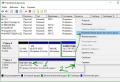
Stage 3: Setting up a debug cable.
When a cable is connected to a computer, it is detected on an unused COM port, its number can be from 1 to 256, in our case the port number is assigned to the cable 26
.

If you need to change the port number, for example, to number 3, go to properties USB Serial Port, select the tab Port parameters, press Additionally, and select the port we need. To save the parameters, click OKif the selected port is already in use, the computer will display a warning: This COM port name is already in use by another device. Duplicate names may result in loss of connection with the device and change of settings. Proceed? , we agree, and click Yes, after that we reconnect the debug cable.

We remember the port number (in our case 26), and start the terminal program. Select the desired COM port, and click Connect, data exchange rate Baud rate set equal 115200 ... If connected correctly, in the status bar (bottom, left) you will see the inscription Connected.
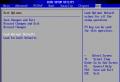
Stage 4: Preparing the printer to receive the firmware.
We turn on the power of the printer. In you will immediately see the information issued by the controller.
Printer needs to be loaded in special mode Monitor Program... To switch to this mode, the printer prompts you to press any key within one second. As soon as you see the inscription in the terminal Press any key to execute Monitor Program within 1 sec ..., you have one second to press any key. If you have time to press, the printer will switch to the desired mode. After that, the printer will ask you about your desire to download from an external port Do you want to download from external port? We politely decline this offer by pressing the " N". The printer enters the command receiving state. pROBE +\u003e.
To update the firmware, enter the command flwhich starts the upgrade flash image. You must enter this command in the lower field of the terminal program. Introduce fl and press Enter.
We prepare a file with firmware and a file loader, for example. Drag the firmware file onto the bootloader file and wait for the printer to update the firmware. After updating, the printer will automatically reboot.
Happy recovery.
| from Sergey 10/25/13 at 10:35 | |
| Hello. Assembled a COM cable powered by USB. When you check the cable like this (On the assembled cable, close the Rx contact to the Tx contact, establish a connection to the COM port in the terminal program, and send data (for example, single characters) to the cable, if they return, then the cable is assembled correctly.) ... I solder it to the ML-2165W printer, I get no response from the printer. Where should the jumper be on the reverse side there is a resistor (I tried to put a jumper). Nothing helped. Tell me where to climb. answer: Are you sure that there is a resistor in place of the jumper? If you arrange the board as we have in the article, then there is a resistor on the right, you do not need to touch it, and on the left there is a place for a jumper. If there are 2 resistors there, then replacing the left one with a jumper should have helped. Perhaps (there were such cases) the jumper looks normal, but in fact it does not close the contact pads. |
#3 |
| from Sergey 02/01/13 at 19:31 | |
| Hello. Not for good reason, the Samsung SCX-3205W MFP stopped printing, although scanning works, it just does not print (the state of the indicator is RED). I took it to the SC, the problem was solved quickly ... by replacing the logic, the masters did not behave unambiguously in communication, they were confused in the testimony, in general I had to doubt their professionalism. Now I would like to check the allegedly out of order logic. Can you tell me how to do this? Thanks. Answer: It is not entirely clear what the masters meant by the term "logic". More precisely, it is completely incomprehensible. The probability that all of a sudden the MFP stopped printing and scans normally is very small. Take the MFP to another SC, and compare the "readings" of both centers. |
#2 |
Related entries:
 How to set up my tele2 unlimited
 The computer does not see the USB flash drive - the reasons and solutions to the problem
 How to connect the Internet for a day from Tele2?
 What to do if the computer does not see the USB flash drive in Windows
 The computer does not see the USB flash drive, what to do


