At what osi level does the switch work. OSI network model. Data streams through the OSI model
OSI Reference Model
For clarity, the process of network operation in reference model OSI is divided into seven layers. This theoretical construction makes it easier to learn and understand rather complex concepts. At the top of the OSI model is the application that needs access to network resources, at the bottom is the network environment itself. As data moves down from layer to layer, the protocols operating at these layers gradually prepare it for transmission over the network. Having reached the target system, the data moves up the levels, and the same protocols perform the same actions, only in reverse order. In 1983 g. International Organization for Standardization (International Organization for Standardization, ISO) and Standardization Sectortelecommunications of the International Telecommunication Union(Telecommunication Standardization Sector of International Telecommunication Union, ITU-T) published the document "The Basic Reference Model for Open Systems Interconnection", which described a model for distributing network functions between 7 different layers (Fig. 1.7). This seven-tier structure was supposed to be the basis for a new protocol stack, but it was never commercialized. Instead, the OSI model is used with existing protocol stacks for training and reference. Most of the protocols popular today appeared before the development of the OSI model, so they do not agree with its seven-layer structure exactly. Often, one protocol combines the functions of two or even several layers of the model, and the boundaries of the protocols often do not correspond to the boundaries of the OSI layers. Nevertheless, the OSI model remains an excellent visual aid for exploring network processes, and professionals often associate functions and protocols with specific layers.
Data encapsulation
In fact, the interaction of protocols operating at different layers of the OSI model manifests itself in the fact that each protocol adds heading(header) or (in one case) trailer (footer) to the information he got from the layer above. For example, an application generates a request for a network resource. This request moves down the protocol stack. When it reaches the transport layer, the protocols of this layer add their own header to the request, consisting of fields with information specific to the functions of this protocol. The original request itself becomes a data field (payload) for the transport layer protocol. By adding its header, the transport layer protocol passes the request to the network layer. The network layer protocol adds its own header to the transport layer protocol header. Thus, for the network layer protocol, the original request and the transport layer protocol header become the payload. This whole construct becomes the payload for the data link protocol, which adds a header and a trailer to it. The result of this activity is package(packet) ready for transmission over the network. When the packet reaches its destination, the process is repeated in reverse order. The protocol of each next layer of the stack (now from bottom to top) processes and removes the equivalent protocol header of the sending system. When the process is complete, the original request reaches the application for which it was intended, exactly as it was generated. The process of adding headers to an application-generated request (Figure 1.8) is called data encapsulation(data encapsulation). In essence, this procedure is similar to the process of preparing a letter to be sent by mail. The request is the letter itself, and adding headers is analogous to putting a letter in an envelope, writing an address, stamping, and actually sending.
Physical layer
At the lowest level of the OSI model - physical(physical) - the characteristics of the elements of the network equipment are determined - the network environment, the installation method, the type of signals used to transmit binary data over the network. In addition, the physical layer determines which type of network adapter to install on each computer and which hub to use (if applicable). At the physical level, we are dealing with copper or fiber optic cable or some kind of wireless connection. On a LAN, the physical layer specifications are directly related to the link layer protocol used on the network. When choosing a link layer protocol, you must use one of the physical layer specifications supported by that protocol. For example, the Ethernet link layer protocol supports several different physical layer options - one of two types of coaxial cable, any twisted pair cable, and fiber optic cable. The parameters of each of these options are formed from numerous information about the requirements of the physical layer, for example, the type of cable and connectors, the allowable cable length, the number of hubs, etc. Compliance with these requirements is necessary for normal work protocols. For example, on an overly long cable, the Ethernet system may not notice packet collisions, and if the system is unable to detect errors, it cannot correct them, the result is data loss. Not all aspects of the physical layer are defined by the data link protocol standard. Some of them are defined separately. One of the most commonly used physical layer specifications is described in the Commercial Building Telecommunications Cabling Standard known as EIA / TIA 568A. It is published jointly American National Institutedarts(American National Standards Institute, ANSI), Associations frombranches of the electronics industry(Electronics Industry Association, EIA) and Communications Industry Association (Telecommunications Industry Association, TIA). This document includes a detailed description of cables for data transmission networks in industrial environments, including minimum distances from sources of electromagnetic interference and other cabling guidelines. Today, cable laying in large networks is most often entrusted to specialized firms. The contractor hired must be familiar with EIA / TIA 568A and similar documents, as well as the city building regulations. Another communication element, defined at the physical layer, is the type of signal for transmitting data over the network medium. For cables with a copper base, this signal is an electric charge, for a fiber-optic cable - a light pulse. Other types of network environments may use radio waves, infrared pulses, and other signals. In addition to the nature of the signals, a scheme for their transmission is established at the physical layer, i.e., a combination electric charges or light pulses, used to encode binary information that is generated by higher levels. Ethernet systems employ a signaling scheme known as manchester encoding(Manchester encoding), and Token Ring systems use differentialmanchester(Differential Manchester) schematic.
Link layer
Protocol channel(data-link) layer provides information exchange between the hardware part of the computer connected to the network and the network software. It prepares for sending to the network the data transmitted to it by the network layer protocol, and transmits to the network layer the data received by the system from the network. When designing and building a LAN, the data link protocol used is the most important factor in the choice of equipment and the method of its installation. To implement the data link protocol, the following hardware and software are required: network interface adapters (if the adapter is a separate device connected to the bus, it is called a network interface card or simply a network card); network adapter drivers; network cables (or other network environment) and ancillary connecting equipment; network hubs (in some cases). Both network adapters and hubs are designed for specific link layer protocols. Some network cables are also tailored for specific protocols, but there are also cables that are suitable for different protocols. By far, today (as always) the most popular data link protocol is Ethernet. Token Ring has lagged far behind, followed by other protocols such as FDDI (Fiber Distributed Data Interface). Three basic elements are typically included in a data link protocol specification: the frame format (that is, the header and trailer added to the network layer data before being sent to the network); access control mechanism to the network environment; one or more physical layer specifications applied with this protocol.
Frame format
The link layer protocol adds a header and a trailer to the data received from the network layer protocol, turning them into frame(frame) (fig. 1.9). To use the postage analogy again, the headline and trailer are the envelope for sending the letter. They contain the addresses of the sending and receiving systems of the packet. For LAN protocols like Ethernet and Token Ring, these addresses are 6-byte hexadecimal strings assigned to the network adapters at the factory. They, unlike addresses used at other layers of the OSI model, are called appa military addresses(hardware address) or MAC addresses (see below). 
NoteThe protocols of the various layers of the OSI model have different names for the structures they create by adding a header to the data coming from the superior protocol. For example, what the link layer protocol calls a frame would be a datagram to the network layer. A more general name for a structural unit of data at any level is package.
It is important to understand that data link protocols only provide communication between computers on the same LAN. The hardware address in the header always belongs to a computer on the same LAN, even if the target system is on a different network. Other important functions of a link layer frame are identifying the network layer protocol that generated the data in the packet and information for detecting errors. Various protocols can be used at the network layer, and therefore a code is usually included in the frame of the link layer protocol, with which you can determine which network layer protocol generated the data in this packet. Using this code, the data link protocol of the receiving computer sends data to the corresponding protocol of its network layer. To detect errors, the transmitting system calculates cyclical cue redundant code(cyclical redundancy check, CRC) of the payload and writes it to the frame trailer. On receiving the packet, the target computer performs the same calculations and compares the result with the contents of the trailer. If the results match, the information was transmitted without errors. Otherwise, the recipient assumes that the packet is corrupted and does not accept it.
Media Access Control
Computers on a LAN usually use a common half-duplex networking environment. In this case, it is quite possible that two computers will start transmitting data simultaneously. In such cases, a kind of packet collision occurs, collision(collision), in which data in both packets is lost. One of the main functions of the data link protocol is media access control (MAC), that is, control over the transmission of data by each of the computers and minimizing packet collisions. The media access control mechanism is one of the most important characteristics of the link layer protocol. Ethernet uses a Carrier Sense Multiple Access with Collision Detection (CSMA / CD) mechanism for media access control. Some other protocols, such as Token Ring, use token passing.
Physical layer specifications
Link-layer protocols used in LANs often support more than one network environment, and one or more physical layer specifications are included in the protocol standard. The link and physical layers are closely related, since the properties of the network environment significantly affect how the protocol controls access to the medium. Therefore, we can say that in local networks the link layer protocols also perform the functions of the physical layer. Wide area networks use link layer protocols that do not include physical layer information, such as Serial Line Internet Protocol (SLIP) and Point-to-Point Protocol (PPP).
Network layer
At first glance it may seem that networkThe (network) layer duplicates some of the functions of the data link layer. But this is not the case: network layer protocols are "responsible" for cross-cutting(end-to-end) communications, while link layer protocols function only within the LAN. In other words, the network layer protocols completely ensure the transfer of the packet from the source to the target system. Depending on the type of network, the sender and receiver may be on the same LAN, on different LANs within the same building, or on LANs thousands of kilometers apart. For example, when you connect to a server on the Internet, on the way to it, packets generated by your computer pass through dozens of networks. By adjusting to these networks, the link layer protocol will change several times, but the network layer protocol will remain the same all the way. The cornerstone of the Transmission Control Protocol / Internet Protocol (TCP / IP) suite and the most commonly used network layer protocol is the Internet Protocol (IP). Novell NetWare has its own IPX (Internetwork Packet Exchange) networking protocol, and small Microsoft Windows networks typically use NetBEUI (NetBIOS Enhanced User Interface). Most of the functions assigned to the network layer are determined by the capabilities of the IP protocol. Similar to the data link protocol, the network layer protocol adds a header to the data it receives from the higher layer (Figure 1.10). A data item created by a network layer protocol consists of transport layer data and a network layer header and is called datagram(datagram).
 |
Addressing
The network layer protocol header, like the link layer protocol header, contains fields with the addresses of the source and target systems. However, in this case, the address of the target system belongs to the final destination of the packet and may differ from the address of the recipient in the header of the link layer protocol. For example, when you enter in address bar browser, the address of the Web site, in the packet generated by your computer, the address of the Web server is specified as the address of the target network layer system, while the data link level the target system indicates the address of the router in your LAN that provides Internet access. IP uses its own addressing system, which is completely independent of link-layer addresses. Each computer on an IP network is manually or automatically assigned a 32-bit IP address that identifies both the computer and the network on which it is located. In IPX, the hardware address is used to identify the computer itself, in addition, a special address is used to identify the network in which the computer is located. NetBEUI distinguishes computers by the NetBIOS names that are assigned to each system during installation.
Fragmentation
Network-layer datagrams must travel through multiple networks on their way to their destination, encountering the specific properties and limitations of various link-layer protocols. One such limitation is the maximum packet size allowed by the protocol. For example, Token Ring frames can be up to 4500 bytes, while Ethernet frames can be up to 1500 bytes. When a large token ring datagram is sent to an Ethernet network, the Network Layer Protocol must split it into multiple fragments of no more than 1500 bytes. This process is called fragmentation(frag mentation). During fragmentation, the network layer protocol breaks the datagram into fragments that are sized to match the capabilities of the data link protocol being used. Each fragment becomes a separate package and continues its path to the target network layer system. The original datagram is formed only after all the fragments have reached the destination. Sometimes, on the way to the target system, the fragments into which the datagram is split have to be fragmented again.
Routing
Routing(routing) refers to the process of choosing the most efficient route on the internetwork for transmitting datagrams from the sending system to the receiving system. In complex Internet networks, such as the Internet or large corporate networks, there are often several paths to get from one computer to another. Network designers deliberately create redundant links so that traffic finds its way to its destination even if one of the routers fails. Routers are used to connect the individual LANs of the internetwork. The purpose of a router is to accept incoming traffic from one network and forward it to a specific system on another. There are two types of systems in the Internet: terminal(end systems) and intermediate(intermediate systems). End systems are the senders and recipients of packets. A router is an intermediate system. End systems use all seven layers of the OSI model, while packets entering intermediate systems do not rise above the network layer. There, the router processes the packet and sends it down the stack for forwarding to the next target system (Figure 1.11).
 |
In order to correctly route the packet to the target, routers store tables with information about the network in memory. This information can be entered manually by the administrator or collected automatically from other routers using specialized protocols. A typical entry in the routing table includes the address of another network and the address of the router through which packets must travel to that network. In addition, the routing table entry contains route metric -conditional assessment of its effectiveness. If there are multiple routes to a system, the router selects the most efficient one and sends the datagram to the data link layer for transmission to the router specified in the table entry with the best metric. In large networks, routing can be unusually complex process, but most often it is done automatically and invisibly to the user.
Transport Layer Protocol Identification
Just as the header of the link layer indicates the network layer protocol that generated and transmitted the data, the header of the network layer contains information about the transport layer protocol from which this data was received. Based on this information, the receiving system sends the incoming datagrams to the appropriate transport layer protocol.
Transport layer
Functions performed by protocols transport(transport) layer, complement the functions of the network layer protocols. Often the protocols of these layers used for data transmission form an interconnected pair, as can be seen from the example of TCP / IP: TCP operates at the transport layer, IP - at the network level. Most protocol suites have two or more transport layer protocols that perform different functions. An alternative to TCP is UDP (User Datagram Protocol). The IPX suite of protocols also includes several transport layer protocols, including NCP (NetWare Core Protocol) and SPX (Sequenced Packet Exchange). The difference between transport protocols from a particular set is that some are connection-oriented and others are not. Systems using the protocol connection-oriented(connection-oriented), they exchange messages before transmitting data to establish communication with each other. This ensures that the systems are on and ready to go. TCP, for example, is connection oriented. When you use a browser to connect to an Internet server, the browser and the server first perform a so-called three-step handshake(three-way handshake). Only then does the browser transmit the address of the required Web page to the server. When the data transfer is complete, the systems perform the same handshake to stop communication. In addition, connection-oriented protocols perform additional actions, such as sending a packet acknowledgment, segmenting data, controlling flow, and detecting and correcting errors. Typically, this type of protocol is used to transfer large amounts of information that should not contain a single bit of error, such as data files or programs. The additional functions of the connection-oriented protocols ensure correct data transfer. This is why these protocols are often called reliable(reliable). Reliability in this case is a technical term and means that each transmitted packet is checked for errors, in addition, the sending system is notified of the delivery of each packet. The disadvantage of this type of protocol is the significant amount of control data exchanged between the two systems. First, additional messages are sent when communication is established and terminated. Second, the header added to the packet by the connection-oriented protocol is significantly larger than the header of the connection-oriented protocol. For example, the TCP / IP header is 20 bytes and the UDP header is 8 bytes. Protocol, connectionless (connectionless), does not establish a connection between two systems before data transfer. The sender simply transmits information to the target system without worrying about whether it is ready to receive data or whether this system even exists. Systems typically rely on connectionless protocols such as UDP for short transactions consisting of only requests and responses. The response signal from the recipient implicitly acts as an acknowledgment signal for the transmission.
Note Connection-oriented and connectionless protocols are not limited to the transport layer. For example, network-layer protocols are usually not connection-oriented because they place the reliability of communication on the transport layer.
Transport layer protocols (as well as network and data link layers) usually contain information from higher levels. For example, TCP and UDP headers include port numbers that identify the application that originated the packet and the application for which it is intended. On session(session) layer, a significant discrepancy begins between the actually used protocols and the OSI model. Unlike the lower levels, there are no dedicated session-level protocols. The functions of this layer are integrated into the protocols, which also perform the functions of the representative and application layers. Transport, network, link and physical layers are engaged in the actual transmission of data over the network. The protocols of the session and higher levels have no relation to the communication process. The session layer includes 22 services, many of which specify how information is exchanged between systems on the network. The most important are the dialogue management and dialogue splitting services. The exchange of information between two systems on a network is called dialogue(dialog). Dialogue management(dialog control) is to select the mode in which the systems will exchange messages. There are two such modes: half duplex (two-way alternate, TWA) and duplex(two-way simultaneous, TWS). In half-duplex mode, the two systems also transmit tokens along with the data. Information can only be transmitted to the computer that currently has the marker. This avoids collision of messages along the way. The duplex model is more complex. There are no markers in it; both systems can transmit data at any time, even simultaneously. Splitting dialogue(dialog separation) consists in including in the data stream control points(checkpoints) to synchronize the operation of the two systems. The degree of difficulty in dividing a dialogue depends on the mode in which it is carried out. In semi-duplex mode, the systems perform a small synchronization of checkpoint messages. In full duplex mode, the systems perform full synchronization using the master / active marker.
Representative level
On representativeThe (presentation) level has only one function: the translation of syntax between different systems. Sometimes computers on a network use different syntaxes. The representative level allows them to "agree" on a common syntax for exchanging data. When establishing a connection at the representative level, the systems exchange messages with information about what syntaxes they have and choose the one that they will use during the session. Both systems participating in the connection have abstractsyntax(abstract syntax) - their "native" form of communication. The abstract syntaxes of different computer platforms may differ. In the process of coordinating the system, a common transfer syntaxdata(transfer syntax). The transmitting system converts its abstract syntax into the syntax of data transfer, and the receiving system, upon completion of the transfer, vice versa. If necessary, the system can choose a data transfer syntax with additional functions, such as data compression or encryption.
Application level
The application layer is the entry point through which programs access the OSI model and network resources. Most application layer protocols provide network access services. For example, the Simple Mail Transfer Protocol (SMTP) is used by most e-mail programs to send messages. Other application protocols such as FTP (File Transfer Protocol) are programs themselves. Session and proxy functions are often included in application protocols. As a result, a typical protocol stack contains four separate protocols that operate at the application, transport, network, and data link layers.
OSI network model (open systems interconnection basic reference model - basic reference model for interconnection of open systems, abbr. EMVOS; 1978) - network model of the OSI / ISO network protocol stack (GOST R ISO / IEC 7498-1-99).
General characteristics of the OSI model
Due to the protracted development of OSI protocols, currently the main protocol stack used is TCP / IP, developed before the adoption of the OSI model and outside of its connection with it.
By the end of the 70s, a large number of proprietary communication protocol stacks already existed in the world, among which one can name, for example, such popular stacks as DECnet, TCP / IP and SNA. This diversity of interworking means has brought to the fore the problem of incompatibility between devices using different protocols. One of the ways to solve this problem at that time was seen as a general transition to a single protocol stack common to all systems, created taking into account the shortcomings of existing stacks. This academic approach to creating a new stack began with the development of the OSI model and took seven years (1977 to 1984). The purpose of the OSI model is to provide a generalized representation of networking tools. It was developed as a kind of universal language for network specialists, which is why it is called a reference model. In the OSI model, communication tools are divided into seven layers: application, presentation, session, transport, network, channel and physical... Each layer deals with a very specific aspect of the interaction of network devices.
Applications can implement their own communication protocols using a multi-level set of system tools for this purpose. For this purpose, programmers are provided with an application software interface (Application Program Interface, API). In accordance with the ideal scheme of the OSI model, an application can make requests only to the uppermost layer - the application layer, but in practice, many communication protocol stacks allow programmers to directly access services, or services below the layers. For example, some DBMS have built-in remote file access facilities. In this case, the application does not use the system file service when accessing remote resources; it bypasses the upper layers of the OSI model and speaks directly to the system tools responsible for transporting messages across the network, which are located at the lower layers of the OSI model. So, suppose the application of node A wants to interact with the application of node B. To do this, application A makes a request to the application layer, for example, the file service. Based on this request, the application software generates a message in a standard format. But in order to deliver this information to its destination, there are still many tasks to be solved, the responsibility for which is borne by the lower levels. After the message is generated, the application layer directs it down the stack to the presentation layer. The presentation layer protocol, based on the information obtained from the header of the application layer message, performs the required actions and adds its own service information to the message - the presentation layer header, which contains instructions for the presentation layer protocol of the destination machine. The resulting message is passed down to the session layer, which, in turn, adds its own header, and so on. (Some protocol implementations put service information not only at the beginning of the message as a header, but also at the end as a so-called trailer.) Finally, the message reaches the lower, physical, layer, which, in fact, transmits it over the communication lines to the destination machine. At this point, the message is "overgrown" with headers of all levels.
The physical layer places a message on the physical output interface of computer 1, and it begins its "journey" across the network (up to this point, the message was transmitted from one layer to another within computer 1). When a message arrives over the network at the input interface of computer 2, it is received by its physical layer and sequentially moves up from layer to layer. Each level parses and processes the header of its level, performing the corresponding functions, and then removes this header and passes the message to the higher level. As can be seen from the description, protocol entities of the same level do not communicate directly with each other, intermediaries are always involved in this communication - means of protocols of lower levels. And only the physical levels of various nodes interact directly.
OSI model layers
| OSI model | ||||
|---|---|---|---|---|
| Layer | ) | Functions | Examples of | |
| Host layers |
7. Application | Access to network services | HTTP, FTP, SMTP | |
| 6. Representative (presentation) | Presentation and data encryption | ASCII, EBCDIC, JPEG | ||
| 5. Session | Session management | RPC, PAP | ||
| 4. Transport | Segments / Datagrams |
Direct connection between endpoints and reliability | TCP, UDP, SCTP | |
| layers |
3. Network | Packets | Route determination and logical addressing | IPv4, IPv6, IPsec, AppleTalk |
| 2. Channel (data link) | Bits (bit) / Frames |
Physical addressing | PPP, IEEE 802.2, Ethernet, DSL, L2TP, ARP | |
| 1. Physical | Bits (bit) | Working with media, signals and binary data | USB, twisted pair, coaxial cable, optical cable | |
In the literature, it is most common to begin describing the layers of the OSI model at the 7th layer, called the application layer, in which user applications access the network. The OSI model ends with the 1st layer - the physical, which defines the standards set by independent manufacturers for data transmission media:
- type of transmission medium (copper cable, fiber optic, radio broadcast, etc.),
- signal modulation type,
- signal levels of logical discrete states (zero and one).
Any protocol of the OSI model must interact either with the protocols of its layer, or with protocols one higher and / or lower than its layer. Interactions with protocols of their own level are called horizontal, and with levels one higher or lower - vertical. Any protocol of the OSI model can perform only the functions of its own layer and cannot perform the functions of another layer, which is not performed in the protocols of alternative models.
Each level, with some degree of conventionality, has its own operand - a logically indivisible data element that can be operated on a separate level within the framework of the model and the protocols used: at the physical level, the smallest unit is a bit, at the data link level, information is combined into frames, at the network level - into packets ( datagrams), on transport - into segments. Any piece of data logically combined for transmission - frame, packet, datagram - is considered a message. It is messages in general that are the operands of the session, presentation, and application levels.
The basic network technologies include the physical and data link layers.
Application level
Application layer (application layer) - the top layer of the model that provides interaction custom applications with network:
- allows applications to use network services:
- remote access to files and databases,
- forwarding email;
- responsible for the transfer of service information;
- provides applications with error information;
- generates requests to the presentation layer.
Application protocols: RDP, HTTP, SMTP, SNMP, POP3, FTP, XMPP, OSCAR, Modbus, SIP, TELNET and others.
Presentation layer
The presentation layer (presentation layer) provides protocol conversion and data encoding / decoding. Application requests received from the application layer are converted into a format for transmission over the network at the presentation layer, and data received from the network is converted into application format. At this level, compression / decompression or encryption / decryption can be performed, as well as redirecting requests to another network resource if they cannot be processed locally.
The presentation layer is usually an intermediate protocol for transforming information from adjacent layers. This allows applications to be exchanged on heterogeneous computer systems in an application-transparent manner. The presentation layer provides formatting and code transformation. Code formatting is used to ensure that the application receives information for processing that makes sense to it. If necessary, this layer can translate from one data format to another.
The presentation layer deals not only with the formats and presentation of data, it also deals with the data structures that are used by programs. Thus, layer 6 ensures that the data is organized in transit.
To understand how this works, let's imagine that there are two systems. One uses EBCDIC extended binary code to represent data, for example, it could be an IBM mainframe, and the other uses American Standard Information Interchange Code (ASCII) (used by most other computer manufacturers). If these two systems need to exchange information, then a presentation layer is needed that will perform the conversion and translate between the two different formats.
Another function performed at the presentation level is data encryption, which is used in cases where it is necessary to protect the transmitted information from access by unauthorized recipients. To solve this problem, the processes and codes at the presentation level must perform data transformation. At this level, there are other routines that compress texts and convert graphic images into bit streams so that they can be transmitted over the network.
Presentation-level standards also define ways of presentation graphic images... For these purposes, the PICT format can be used - an image format used to transfer QuickDraw graphics between programs.
Another representation format is the tagged TIFF image file format, which is commonly used for high-resolution bitmaps. The next presentation level standard that can be used for graphics is the standard developed by the Joint Photographic Expert Group; in everyday use this standard is simply referred to as JPEG.
There is another group of presentation-level standards that define the presentation of sound and film. This includes a Musical Instrument Digital Interface (MIDI) for digital presentation of music, an MPEG standard developed by the Cinematography Expert Group, used to compress and encode video clips on CDs, digitize storage, and transfer at speeds up to 1.5 Mbps, and QuickTime is a standard that describes audio and video elements for programs running on Macintosh and PowerPC computers.
Presentation layer protocols: AFP - Apple Filing Protocol, ICA - Independent Computing Architecture, LPP - Lightweight Presentation Protocol, NCP - NetWare Core Protocol, NDR - Network Data Representation, XDR - eXternal Data Representation, X.25 PAD - Packet Asser / Disassembler Protocol ...
Session level
The session layer of the model provides maintenance of the communication session, allowing applications to interact with each other for a long time. The layer manages session creation / termination, information exchange, task synchronization, determination of the right to transfer data and maintaining a session during periods of inactivity of applications.
Session layer protocols: ADSP (AppleTalk Data Stream Protocol), ASP (AppleTalk Session Protocol), H.245 (Call Control Protocol for Multimedia Communication), ISO-SP (OSI Session Layer Protocol (X.225, ISO 8327)), iSNS (Internet Storage Name Service), L2F (Layer 2 Forwarding Protocol), L2TP (Layer 2 Tunneling Protocol), NetBIOS (Network Basic Input Output System), PAP (Password Authentication Protocol), PPTP (Point-to-Point Tunneling Protocol), RPC (Remote Procedure Call Protocol), RTCP (Real-time Transport Control Protocol), SMPP (Short Message Peer-to-Peer), SCP (Session Control Protocol), ZIP (Zone Information Protocol), SDP (Sockets Direct Protoco]) ...
Transport layer
The transport layer of the model is designed to provide reliable data transfer from sender to receiver. In this case, the level of reliability can vary widely. There are many classes of transport layer protocols, ranging from protocols that provide only basic transport functions (for example, data transfer functions without acknowledgment of receipt), and ending with protocols that guarantee the delivery of multiple data packets in the correct sequence to the destination, multiplex multiple data streams, provide a data flow control mechanism and guarantee the validity of the received data. For example, UDP is limited to monitoring the integrity of data within a single datagram, and does not exclude the possibility of losing an entire packet, or duplicating packets, violation of the order of receiving data packets; TCP provides reliable continuous data transfer, excluding data loss or out of order of their arrival or duplication, can reallocate data, breaking large chunks of data into fragments and vice versa, gluing the fragments into one packet.
Transport layer protocols: ATP (AppleTalk Transaction Protocol), CUDP (Cyclic UDP), DCCP (Datagram Congestion Control Protocol), FCP (Fiber Channel | Fiber Channel Protocol), IL (IL Protocol), NBF (NetBIOS Frames protocol), NCP ( NetWare Core Protocol), SCTP (Stream Control Transmission Protocol), SPX (Sequenced Packet Exchange), SST (Structured Stream Transport), TCP (Transmission Control Protocol), UDP (User Datagram Protocol).
Network layer
The network layer (lang-en | network layer) of the model is used to define the data transmission path. Responsible for translating logical addresses and names into physical ones, determining the shortest routes, switching and routing, tracking problems and "congestion" in the network.
Network layer protocols route data from source to destination. Devices (routers) operating at this level are conventionally called third-level devices (by the level number in the OSI model).
Network layer protocols: IP / IPv4 / IPv6 (Internet Protocol), IPX (Internetwork Packet Exchange), X.25 (partially implemented at layer 2), CLNP (connectionless network protocol), IPsec (Internet Protocol Security). Routing protocols - RIP (Routing Information Protocol), OSPF (Open Shortest Path First).
Link layer
The data link layer is designed to ensure the interaction of networks at the physical layer and to control errors that may occur. The data received from the physical layer, presented in bits, it packs into frames, checks them for integrity and, if necessary, corrects errors (generates a repeated request for a damaged frame) and sends it to the network layer. The link layer can interact with one or more physical layers, controlling and managing this interaction.
The IEEE 802 specification divides this layer into two sublayers: MAC (Media Access Control) regulates access to the shared physical medium, LLC (logical link control) provides network layer services.
Switches, bridges, and other devices operate at this level. These devices are said to use layer 2 addressing (by layer number in the OSI model).
Link layer protocols: ARCnet, ATM (Asynchronous Transfer Mode), Controller Area Network (CAN), Econet, IEEE 802.3 (Ethernet), Ethernet Automatic Protection Switching (EAPS), Fiber Distributed Data Interface (FDDI), Frame Relay, High-Level Data Link Control (HDLC), IEEE 802.2 (provides LLC functions to IEEE 802 MAC layers), Link Access Procedures, D channel (LAPD), IEEE 802.11 wireless LAN, LocalTalk, Multiprotocol Label Switching (MPLS), Point-to-Point Protocol (PPP), Point-to-Point Protocol over Ethernet (PPPoE), StarLan, Token ring, Unidirectional Link Detection (UDLD), x.25]], ARP.
In programming, this layer represents the driver of the network card, in operating systems there is a software interface for the interaction of the channel and network layers with each other. Is not new level, but just an OS-specific model implementation. Examples of such interfaces: ODI, NDIS, UDI.
Physical layer
The physical layer is the lower layer of the model, which defines the method of transferring data represented in binary form from one device (computer) to another. Various organizations are involved in the compilation of such methods, including: the Institute of Electrical and Electronic Engineers, the Electronics Industry Alliance, the European Telecommunication Standards Institute, and others. They transfer electrical or optical signals to a cable or radio air and, accordingly, receive and convert them into data bits in accordance with the methods of coding digital signals.
Hubs]], signal repeaters and media converters also operate at this level.
Physical layer functions are implemented on all devices connected to the network. On the computer side, the physical layer functions are performed by a network adapter or serial port. The physical layer includes the physical, electrical, and mechanical interfaces between two systems. The physical layer defines such types of data transmission media as optical fiber, twisted pair, coaxial cable, satellite data transmission channel, etc. The standard types of network interfaces related to the physical layer are :)
Related entries:
 Presentation on the topic "social structure and social relations" Social stratification by Weber
 The rapid development and expansion of the fields of application of electronic devices is due to the improvement of the element base, - presentation
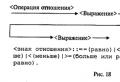 Boolean values, operations, expressions
 Von Neumann architecture presentation
 The history of the development of computer technology The beginning of the computer era


